Alexander Makhov,
M. May, August 2004 (2nd edition)
I opened V.S. Grebennikov’s book “My World” in search of a description of his flying platform, and found myself in another - a fairy-tale world. I just read it to the last page in one breath and realized that this world, the natural world, was really the main thing for the author, and not some kind of flying machine. The device is secondary, it is only a delivery vehicle to his world.
Modern life coarsens sensory perception. A person, it seems to him, should be rational in his thoughts and actions, but blatant poverty makes him think about his daily bread, and then there are bugs, boogers, dolls...
And, nevertheless, only thanks to people like V.S. Grebennikov, a person awakens the consciousness of involvement in something very important and at the same time - something deeply personal, a nagging pain arises about something irrevocably lost...
What about the platform?
I’ll be honest, I didn’t really want to write this article. For myself, I figured out the essence of this LA a long time ago. Let others say that V.S. Grebennikov’s book contains too meager a list of technical data to not only build such a device, but also to believe in the possibility of its existence. And for me, this information is more than enough. And even though the necessary information is “scattered” throughout the book, among the text and pictures, it is there!
Another motivation for writing the article was the need to protect the good name of V.S. from attacks from unscrupulous individuals (I don’t even want to use the word “people”), from priests from official science, from religion. This is necessary, a special committee has been created at the Russian Academy of Sciences on the so-called. “the fight against pseudoscience”, a real scientific inquisition!
Another reason that prompted me to take up the pen was the numerous publications on the Internet about the so-called “decoding” of the design of the flying platform, which have nothing to do with reality. Here I simply decided: there is already enough misinformation around vortex devices, we cannot continue to tolerate new fabrications.
1. Grebennikov platform and its prototypes
For those who have not yet had time to familiarize themselves with this wonderful book, it may be recalled that Viktor Stepanovich Grebennikov, a Siberian entomologist, studied the effect of cavity structures in insects. This is what he called the mysterious radiation emanating from their nests.
In part 5-1 of the book, he writes: “I only have a handful of old clay lumps left - fragments of those nests - with numerous closets and cells. The cells were located side by side and resembled small thimbles, or rather jugs with smoothly tapering necks; I already knew that these bees belong to the species Galikt four-banded - by the number of light rings on their oblong abdomen.
On my work table, filled with instruments, houses of ants, grasshoppers, bottles of reagents and all sorts of other things, there was a wide vessel filled with these spongy lumps of clay. I needed to take something, and I carried my hand over these holey debris. And a miracle happened: above them I suddenly felt warmth... I touched the lumps with my hand - they were cold, but above them there was a clear feeling of warmth; In addition, some tremors, twitchings, and “ticks” that were previously unknown to me appeared in my fingers.
And when I moved the bowl with the nests to the edge of the table and bowed my face over it, I felt the same thing as on the Lake: as if my head was becoming light and big, big, my body was falling somewhere down, there were spark-like flashes in my eyes, in my mouth. - taste of battery, slight nausea...
I put a cardboard on top - the sensations are the same. The lid of the pan is as if it’s not there, and this “something” pierces right through the barrier.
The phenomenon should have been studied immediately. But, alas, the instruments did not respond to them at all: neither the most accurate thermometers, nor ultrasound recorders, nor electrometers, nor magnetometers.
But hands, ordinary human hands - and not just mine! - they clearly felt above the nesting places either warmth, or a kind of cold breeze, or goosebumps, or ticks, or a thicker environment, like jelly; For some, the hand felt “heavy”; for others, it was as if something was pushing it up; some had numb fingers, cramped forearm muscles, dizziness, and salivation profusely.”
But how did V.S. Grebennikov come up with the idea of his aircraft?
We read further: “In the summer of 1988, looking through a microscope at the chitinous covers of insects, their feathery antennae, the finest scales of butterfly wings, the lacy wings of lacewings with iridescent iridescence and other Patents of Nature, I became interested in the unusually rhythmic microstructure of one of the rather large insect parts. It was an extremely orderly composition, as if stamped on some complex machine according to special drawings and calculations. In my opinion, this incomparable cellularity was clearly not required either for the strength of this part or for its decoration.
I have not observed anything even remotely reminiscent of this unusual, amazing micropattern either in other insects, or in the rest of nature, or in technology or art; Because it is three-dimensional, multidimensional, I have still not been able to reproduce it in a flat drawing or photo. Why does an insect do this? Moreover, this structure - the bottom of the elytra - is almost always hidden from other eyes, except in flight, when no one can see it.
I suspected: is this a wave beacon that has “my” effect of multi-cavity structures? In that truly happy summer, there were a lot of insects of this species, and I caught them in the evenings in the light; neither “before” nor “after” I observed not only such a large number of them, but also individual individuals.
I placed this small concave chitinous plate on the microscope table to once again examine its strange stellate cells under high magnification. I admired the jeweler’s next masterpiece of Nature, and almost without any purpose, I put on it with tweezers another exactly the same plate with these extraordinary cells on one of its sides.
But that was not the case: the part escaped from the tweezers, hung in the air for a couple of seconds above the one on the microscope table, turned a little clockwise, and slid down - through the air! - to the right, turned counterclockwise, swayed, and only then quickly and sharply fell onto the table.
What I experienced at that moment - the reader can only imagine...
Having come to my senses, I tied together several panels with wire; this was not easy, and only when I took them vertically. The result was a multi-layered “chitinoblock”. He put it on the table. Even such a relatively heavy object as a large pushpin could not fall on him: something seemed to knock it up and then to the side. I attached the button on top to the “block” - and then such incongruous, incredible things began to happen (in particular, for some moments the button completely disappeared from view!) that I realized: this is not a beacon, but something completely, completely different.
And again my breath was taken away, and again from excitement all the objects around me floated as if in a fog; but, although with difficulty, I finally pulled myself together, and after two hours I was able to continue working...
In fact, it all started from this incident.”

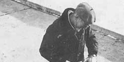
Grebennikov's gravity plane
And after 2 years of painstaking work, the gravitoplane shown in the photograph appeared - an aircraft with amazing characteristics. It is invisible to others, does not require a traditional engine in our understanding, has neither a wing nor a propeller, is silent, easily develops a safe flight speed of 1500 km/h, which is not felt by the pilot, there are absolutely no inertial properties of the moving body, there is no thermal the impact on the aircraft of ambient air, speed pressure and many other qualities. And it looks very simple - a stand with two handles, mounted on an open sketchbook.
The inventor did not come up with the idea of the possibility of creating a vortex aircraft out of nowhere. In many places in his book he describes the remarkable properties of the elytra of the scarab, the goldenrod, and especially the bronze beetle. In essence, the elytra are the supporting system of the insect.
How can we adapt it to human needs?
Yes, simple. It is necessary to create a unit cell, geometrically similar to an insect cell, that would create thrust, and then combine the required number of these cells into panels. Here's the aircraft's load-bearing system!
Scarab in flight
Theorizing, we note that such a mini-aircraft can have a single or combined carrier system. Here, in all cases (vertical, horizontal flight, climb or descent), a vortex propulsion is used, but insects also use a wing in forward flight. In the scarab and bronze beetle, it is rigid, similar in design to an open umbrella, and, unlike the borer, does not use swinging movements. In this case, an auxiliary lifting force is created on the wing, and some deformation of the wing allows the insect to control the direction of flight and stabilize its body in space.
Hence, when determining the aircraft layout, the designer must make a choice about the need to use a wing. In this case, the determining factor will be the maximum speed of the future aircraft.
Here, apparently, we need to dwell on this point in more detail. The whole point is that various parts of our aircraft can be in flight both in a homogeneous environment, for example, the physical one that is familiar to us, and in heterogeneous environments.
Conventional aircraft move only in a physical environment - an environment of weak torsion fields. But Grebennikov’s platform in flight is already completely in a different environment - an environment of intense torsion fields. Why “fields” and not “fields” - this will become clear later, but for now...
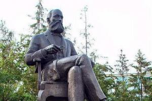
It is known that an intense torsion field (ITF) has a number of features: an aircraft, being in it, can develop enormous flight speeds without subjecting it to any inertial and thermal overloads; An aircraft surrounded by such a field can abruptly change the direction of its movement at high speed, without any damage to the structure and crew. A body located in ITP acquires the qualities of its invisibility for the observer. Matter cannot penetrate through this field, but at the same time, air and the electromagnetic field of both high and low frequencies, including light and the electromagnetic field of the Earth, pass through. ITP is accompanied by electromagnetic radiation of ultra-high frequency, exposing photographic film, discharging storage sources of electrical energy and adversely affecting the biological cells of the body. As a concomitant phenomenon, a special effect on minerals containing quartz can be noted. Thus, V.S. Grebennikov’s glass test tubes were destroyed and “burned” during flight; he notes cases of the appearance of holes melted along the edges in window glass. This also includes the so-called megalithic “mysteries” associated with the movement and rise of massive stone pillars, statues, and blocks in ancient times, based on which the most incredible hypotheses are still being born - everything except the correct one. And the answer is in the tetrahedron structure of quartz crystals, which are easily excited by an external torsion source, turning into a mini-aircraft, and the stone loses weight!
The aircraft wing, protruding beyond the ITP boundary, is in a normal air environment, where it experiences all known loads: velocity pressure, inertial forces, thermal and electrostatic effects.
What happens at the border of the two environments is unknown today, but the fact that the structure remains viable is evidenced by the flight of our good friends beetles - the scarab and the bronze beetle. This means that the main conclusion is that such devices have the right to life, they can be built!

Bronze wing and elytra
2. Support system
The supporting system is, in fact, the platform's mover.
Let us immediately note that the propulsion is vortex, passive type. This means that the creation of thrust is based on an electromagnetic vortex, and only a vortex formed by the design of the aircraft's supporting system. The passive type of propulsion, in contrast to the active one, implies that an internal source of energy is not required to create a vortex “thrust” - this “thrust” is created only due to the energy of the environment.
The supporting system consists of several panels. The number of panels, depending on the design of the aircraft, can be varied, but there may be only one panel in it. For example, in V.S. Grebennikov’s platform there are 4 of them, but in the book he also mentioned his thoughts about installing 3 or 4 panels.
General requirements for the number of panels:
· they must provide the required amount of total thrust, both in vertical and horizontal flight of the aircraft;
· in the absence of special (additional) elements of the aircraft - to ensure conditions for stability and controllability of the device (stabilization and change of position in space).
We will come to the design options for the panels later, but now we will consider the design of an elementary vortex funnel (cell).

“Carrying system” of the golden borer (bottom view of the elytra - enlarged)
3. Vortex cell
The vortex cell is the primary element of the supporting panel, a mini-propeller. Like any vortex device, this propulsion device has a shaper, a resonator, an ionizer and a drain (see “Vortex - the weapon of the gods”).
A funnel-shaped cavity, working in tandem with the Earth’s magnetic field, serves as a vortex former. In order for a vortex to be born and function, it must be tuned to one of the harmonics of the planet’s magnetic field. This function is implemented by a resonator - the same funnel, but having strictly defined dimensions (see the same work). It follows that the geometric dimensions of the funnels form a stepped series, where there is no place for intermediate values. This is how the natural cosmic frequency (NCF) of our planet manifests itself (see “Why does the Earth rotate?”).

View of the cells from the socket side
The ionized medium is air, and artificial ionization is not required on a hot summer day. By the way, V.S. Grebennikov also mentions this.
The scarab also uses heating the air to ionize it, eating a ball of horse manure before flying, thereby raising its body temperature, as given in one of the sources, from 27 to 41 ° C. Compare with our actions in a country greenhouse: to intensively heat the spring soil, we make sure to lay the bottom layer of manure, preferably horse manure, thereby using its high calorific value.
By the way, the great Fabre, who devoted more than a dozen years to the study of scarabs, only at the end of his long life established that the scarab makes its pear-shaped nest for breeding offspring from SHEEP manure, and not HORSE manure. Skeptics - what do you say to this?
But let's return to ionization. In other cases, artificial ionization of air can be used; the easiest way to make such an ionizer is with an electric spark (for example, an ordinary piezoelectric lighter for gas stoves). Often, artificial ionization is required only at the moment of launching the vortex device, and only for one cell of the panel. The remaining cells will already start from the working one. Subsequently, on the ground and in flight, the required level of ionization is maintained automatically due to the friction of the air particles of the vortex among themselves and against the walls of the funnel. This is also facilitated by an increase in the electrostatic potential of the vortex, again due to the “suction” of static electricity along the vortex cord from the atmosphere (remember - the change in the electric potential of the Earth’s field is ~130 V/m?).
When the medium is ionized, the working “body” of the vortex is positive ions formed during the splitting of air molecules.
Where do the negative ions go?
They accumulate on the inner walls of the funnel, flowing down to the edges of its wide bell. And, if you don’t ensure their drainage, the funnel will simply “choke”, receiving a negative charge, and stop working. Elements of drainage can be observed in the same scarab - in the form of thin hairs. Drainage devices are also shown in images of aircraft of foreign civilizations of antiquity. The plumage of birds is also a drainage device. The feather headdress of the American Indians is an echo of their connections with the “gods” of these civilizations. I suspect that the hair of people and animals is nature’s concern for ridding the biological organism of excess static electricity.
Let's try to determine the energy capabilities of an elementary cell. V.S. Grebennikov writes about his 75 kg, which had to be lifted into the air, plus the weight of the apparatus. By adjusting this figure taking into account the margin for a decrease in thrust with increasing flight altitude, as well as for the possibility of performing forward flight, we will set the calculated thrust level at 100 kg.
There were 4 corner panels installed on its platform, and, according to my estimates, each panel had 16-20 cells. In total there are 64-80 of them.
Then the specific thrust of each cell should be in the range of 1.60 - 1.25 kg. This is an important indicator that will be required when making your own panels.
The second figure of the cell's power supply can be approximately determined based on statistical data on the specific thrust of various helicopters, correlating the available engine power to the maximum flight weight. Approximately it will be ~150 W/kg.
Then, per 100 kg of flight weight, the total power developed by the platform’s supporting system can be determined to be approximately 15 kW, and the specific power of the elementary cell will be approximately equal to 200 W/cell.
These figures give a clear idea of what electrical power (in the form of alternating or direct current) can be removed from the vortex carrier system, using it in whole or in part as an energy source (for example, to power on-board equipment). 
Cell design.
Structurally, the cell is a funnel-shaped cavity formed by the inner walls of the funnel and a reflective surface. The funnel, naturally, has a certain wall thickness - it is minimal and is determined from strength considerations. The characteristic sections of the funnel are the bell (wide part) and the “eye” (narrow neck). On the outer surface of the funnel there is a spiral winding of metal conductors.
Calculation of cell parameters. As mentioned earlier, the geometry and methodology for calculating the cell are set out in the work “Whirlwind - Weapon of the Gods”, it is simple, and there is no point in repeating it. It is only necessary to note that the basic parameter is the frequency of the 1st harmonic of the Earth's magnetic field. According to different sources, the numbers differ: according to some it is 7.50Hz, according to others – 7.83Hz.
Determining optimal cell sizes.
Let us select diameter D (top line) from the table below as the initial theoretical standard size. Next, in the range of 10.55...11.02, with some reserve, we will assign a number of test sizes, for example, in increments of 0.1 mm (10.45; 10.55; 10.65; 10.75; 10.85; 10.95; 11.05; 11.15). The value of Δ will practically not change and will be equal to 0.07 for the entire series. To determine the value of R0, it is necessary to use the previously given formula for the relationship between these parameters D = 2(R0 + Δ).
If cells with these sizes do not self-excite, you will have to sequentially move to rows 2, 3 and 4 of the table. It should be remembered that the larger the cell, the less its ability to self-excite. But small cells are more difficult to create, hence the need to find the largest possible size.
Cell tests.
The main direction of the tests is to determine the specific thrust of the cell. As an additional parameter, you can determine the magnitude of the moment of reversal of the cell from the elementary vortex.
The test setup is based on elementary scales. Here everything is left to the testing imagination. We only note that the cell must be suspended vertically, with its “eye” up. We connect the cell drain wire to the ground loop. To reduce torsion pollution in the room, the axis of the vortex should be directed inside the section of the grounded metal pipe. It is possible to suspend a scale cup with weights from the cell body. If the cup is located directly under the cell, then it must have a central hole for the passage of the vortex axis into the grounding pipe.
And one last thing. The suspended cell must have degrees of freedom selected for lateral displacements and axial rotation.
Having set the measuring device to the zero position (naturally, taking into account the weight of the cell itself), we ionize the cell in the plane of its bell using the mentioned gas lighter. The cell should start, which the scales will immediately show.
Note: If the cell is self-excited, then to turn it off during the preparatory stages it is necessary to remove the reflective surface.
By equalizing the scales using weights until the moment of balance, we thereby determine the value of the specific thrust for a given cell size.
By repeating the tests for the remaining standard sizes of the series, from a series of cells that self-excite under normal conditions, we will find the cell with the maximum specific thrust. Its geometric characteristic is the optimal cell size.
4. Panel configuration and full thrust control principle
The panel configuration can be different: triangular, rectangular, arc, etc. Its choice depends entirely on the design of the aircraft's supporting system.
But there are general requirements, of which the first 2 are advisory in nature, and the last is mandatory:
· the number of cells N must satisfy the given formula for the parity of rows and columns;
· each panel must have an equal number of cells with vortices of left and right rotation;
· control of the overall thrust of the aircraft's supporting system must be carried out in such a way that, at any position of the control element, a unfolding reactive torque does not arise from the operating cells of all panels.
This explains the principle of full thrust control - turning on and off some of the cells of the supporting system.
5. Sketch (plaz) synchronization
There are several points that many modern inventors of vortex technology cannot overcome:
· misunderstanding of the importance of drain, and, as a result, the cell starts and then stops working;
· ignorance of the stepwise geometric dimensions of the cells, ignorance of the ideal shape and dimensions of the vortex cell, i.e. her mathematicians;
· lack of information about the size paradox, when small cells work well, but after a certain threshold, as their sizes increase, they stop self-exciting. This even led to some skepticism in the inventive community, saying that vortex technology is only suitable for models or toys, while industrial designs cannot work. I answer them in the affirmative: yes, this is exactly the moment when the cell needs to be transferred from the self-excitation mode to the external ionization mode;
· so far no one (at least in open Internet sources) has been able to read about an attempt to force self-excited or small cells to work in parallel, combining their powers into one - to solve a single problem. Moreover, no one has even formulated the problem of compensation for the reactive moments of elementary vortices.
The last problem was successfully solved by V.S. Grebennikov, honor and glory to him! But he is not an electronics engineer, not a technician, but he solved the problem... Directly from V.S. there is not a word about synchronization, but there is a drawing...
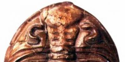
And only Grebennikov rediscovered the true value of the scarab, about which we have been fooled in all sources for several thousand years. You see, they say that the scarab is deified for the allegory of the Universe that this beetle symbolized when it rolled its ball of dung. Read about the scarabs of Egypt, and you will not find a different opinion there. But the first pharaohs and their priests knew the truth perfectly, and the current priests also know it, but they keep quiet!

Holy Scarab
6. Manufacturing of panels
Due to two determining factors - the specific direction of rotation of each vortex and the synchronization of the rotation frequencies of the vortices, carried out electrically, metal cannot be used as the selected cell material.
These factors were determined earlier, but now we will try to formulate the requirements for the panel.
Obviously, the rigidity and lightness of the structure must be ensured and there must be no porosity. The inner surface of the funnel must have good aerodynamics, and the material must work well in microwave electromagnetic fields.
All of the listed properties are well met by plastic, so we will operate with it.
1. From sheet plastic, 0.3-0.5 mm thick, using its processing technologies (shapes, pressure, heat treatment, etc.), we will produce a honeycomb panel of a given configuration. I won’t go into details; an inquisitive inventor can easily find the required information on the same Internet network.
2. On the outside of the cells, strictly observing the sketch of the synchronization circuit, the initial phasing, the order of the wires and the exponential nature of the pitch of the turns, glue the pieces of synchronization wires. The wire is copper, in varnish insulation; inter-wire short circuits are not allowed. The diameter of the wire is convenient for installation and provides sufficient tensile strength with some warping of the structure.
3. Now the panel structure can be slightly strengthened by filling the surface of the cells from the side of the wires with a thin layer of some transparent compound. Then we will enclose the panel in a power (non-metallic) frame, with the help of which it will be installed in the structure of the aircraft’s supporting system.
4. Again, from the side of the compound layer, for fear of damaging the synchronization wires, we drill several holes around the bell of each cell. The holes may be of small diameter; hairs of drainage from the funnels will be passed through them.
5. We strengthen the panel again, increasing the layer of compound on the surface of the cells to a thickness of 1.0-1.5 mm, and a little more in the recesses between them. At the moment of hardening of the new layer on the surface of the funnels, we insert several biohairs into the compound for each cell (drain from the outer surface). We take all measures to prevent warping of the structure.
6. From the side of the cell funnels, use the drill again to follow the existing marks of the filled holes. Insert several biohairs into each hole to ensure drainage from the inner surface of the funnels.
7. Fan out and glue the ends of the biohairs to the sockets of the funnels.
8. Glue the fringe of the drain wiring harness along the non-working length of the power frame (not falling under the plane of the shutter disk). This harness will serve us to ground the panel during testing. In the final state, instead of wires, a fringe of biohairs should also be glued to the frame.
The panel is ready for testing.
7. Aircraft flight control
Aircraft full thrust control– provides vertical flight and flight in climb and descent modes. We have examined the principle of full thrust control; it is ensured by rotating the shutter disk (for V.S. Grebennikov, by a general rotation of the fan elements of the blinds). It should be noted that in the design described here it is desirable to provide not a smooth, but a stepwise change in the angle of rotation of the shutter. This will eliminate any uncertainty in the operation of the cells.
Longitudinal and lateral control– provides forward flight, respectively, forward-backward or left-right, as well as a turn.
V.S. Grebennikov solves the problem, as I understand it, by bending the fan elements of the blinds (by changing the gap between the plane of the fan and the plane of the soles of the funnels).
Another solution is proposed here: install a set of panels together with a shutter inside a two-frame gimbal. Then the rotation of one frame will cause the support system to tilt in one direction, for example, in the longitudinal direction, and the rotation of the other in another, in this example, in the transverse direction.
The longitudinal-transverse control in this design can be easily combined with a single control stick (like a helicopter, fighter, joystick). When such a handle is deflected in intermediate directions, both frames of the suspension will deflect at once, and the full thrust vector will rotate in the required direction. Perhaps, after flight tests, the experience of building helicopters will be useful, when in order to ensure independent control it was necessary to slightly rotate the gimbal assembly in azimuth.
Note: I suspect that, unexpectedly for himself, V.S. Grebennikov could use his own body to turn the aircraft, removing one or another hand from the control column.
It is clear that any impact on the longitudinal-transverse controls will cause a decrease in lift, which can be compensated by the impact on the full thrust controls - an exact analogy of the physical environment of the aircraft.
Note that the angles of deviation of the frames are calculated in several units of degrees. Excessive deflection is high speed, which may be unsafe. In this regard, deflection limiters can be installed on the suspension frames. If longitudinally the control chain must be fixed in flight in an intermediate (not neutral) position, then lateral control is characterized by its short-term use - for setting or course correction. In this regard, the lateral control chain can be fixed in neutral using two counter-tensioned springs. If desired, the same springs, but controlled (trimmer effect), can also be installed in the longitudinal control circuit.
To increase the stability of the aircraft, as an option, the panels and the shutter can be made volume-convex, similar to the shape of the elytra of insects.
8. Security issues
Flight safety is ensured, first of all, by the reliability and simplicity of the aircraft design. The second determining factor is maximum flight speed - this and all other factors are unexplored.
V.S. Grebennikov also cites strict adherence to the cleanliness of the aircraft platform as one of the measures to ensure flight safety. This is understandable: since the ITP does not allow the substance to enter itself, then it should also prevent its release outside. And where should he go? But only in hundreds of cells - and this is their destruction, and, therefore, a disaster. It is clear that this applies not only to small particles, but also to attempts to throw an object out.
Flying in a vortex aircraft also poses a huge biological danger, which V.S. Grebennikov experienced himself. This is, first of all, the effect of microwave radiation on the body. So, flying on such a device is the same as being under the beam of a nearby radar antenna, or spending several hours under X-ray radiation, or walking in the zone of the exploded Chernobyl reactor.
For these reasons, it is best to use such a device in unmanned mode. But this is a slightly different topic.
Viktor Stepanovich Grebennikov is an enthusiastic entomologist, his area of interest is insects. But one day he made an unexpected discovery, which he described in sufficient detail and honestly in the book “My World,” published in Novosibirsk with a circulation of only one thousand copies.
An amazing discovery occurred in the summer of 1988, when a scientist looked at the chitinous covers of a cockchafer through a microscope. He was struck by the pattern on the inside of the wing - it was an ordered, as if stamped, composition, reminiscent of a honeycomb of bees. It would be difficult to understand why nature needed to create such an exquisite structure if it were not for chance.
The researcher, without any purpose, placed exactly the same plate with unusual cells on one plate. And then a strange thing happened: the part escaped from the tweezers, hung in the air for a couple of seconds, and then smoothly fell onto the table. The plates were clearly interacting! Viktor Stepanovich repeated the experiment - one plate hovered above the other!
After this, the scientist fastened several wings with a wire, obtaining a “chitinoblock” - and here not only light objects, but even a pushpin easily hovered over the “block”, and at some point it even completely disappeared from view, as if it had gone into another measurement. Grebennikov realized that he had accidentally stumbled upon something Else: he had discovered the phenomenon of antigravity! Later, the scientist called his discovery the effect of cavity structures.
 Grebennikov carefully examined the structure of the wing substrate under a microscope and managed to replicate it on a prototype. It took him two years to make a compact flying platform for one person from his artist’s easel and a stand attached to it with control over the sectors of overlapping cavity structures.
Grebennikov made his first flight on the night of March 17-18, 1990 from the street VASKHNIL - a town (agricultural academy) near Novosibirsk, where he lived.
 This is how he describes his first flight: “I rose straight from the street, believing that at two o’clock in the morning everyone was asleep and no one could see me. The ascent seemed to start normally, but after a few seconds, when the houses with rare luminous windows went down and I was about a hundred meters above the ground, I felt sick, as if about to faint. I would have lowered myself here, but I didn’t do it, and in vain, since some powerful force seemed to wrest control of movement and gravity from me - and inexorably dragged me towards the city.”
He crossed the zone of nine-story buildings, flew over a snow-covered field, the Novosibirsk-Akademgorodok highway and rushed towards the bulk of the sleeping city. He was carried towards the factory chimneys, smoking thickly in the night.
“With the greatest difficulty, I was able to make an emergency reconfiguration of the block panels with barely half an hour,” writes Viktor Stepanovich. — The horizontal movement began to slow down. Only on the fourth time did I manage to extinguish it and hover over Zatulinka - the Kirovsky district of the city... Having made sure with relief that the “evil force” had disappeared, I slid back, but not towards the VASKHNIL-town, but to the right, towards Tolmachev - to confuse the trail in case , if someone noticed me."

The next day, the news, messages on television and in newspapers were more than alarming for the tester. Headlines “UFO over Zatulinka”, “Aliens again?” — they clearly said that his flight had been detected. Some perceived the “phenomenon” as luminous balls or disks, others claimed that a “real saucer” was flying with portholes and rays...
Since then, the inventor began to improve his “apparatus,” sometimes undertaking very long journeys, up to 400 km, to natural reserves, where he continued to study insects. As a rule, flights took place in the summer.
Gennady Moiseevich Zadneprovsky talked about this, showing on the screen photographs of Grebennikov himself, his strange apparatus, and photos of the platform taking off. Frankly, even we, ufologists, accustomed to a variety of situations and surprises, found it difficult to grasp the reality of such a discovery.
This is how Grebennikov himself describes his flights:
 — A hot summer day. The distances are buried in a bluish-lilac haze. I’m flying about three hundred meters above the ground, taking the distant lake as a reference point—a light, elongated speck in the foggy haze. Paths wind between fields and copses. They run towards the dirt roads, and they, in turn, stretch there, towards the highway... Now I am in the shadow of a cloud; I increase my speed - it’s very easy for me to do this - and fly out of the shadows... It’s not the rising currents that keep me in the air, I don’t have wings; in flight, I rest my feet on a flat rectangular platform, slightly larger than the lid of a chair - with a stand and two handles, which I hold on to and with the help of which I control the device. Fantastic? How can I say...
“You can’t see me from below: even when flying very low, for the most part I don’t cast a shadow at all.” But still, as I later learned, people occasionally see something in this place in the sky: either a light ball or disk, or a semblance of a vertical or oblique cloud with sharp edges, moving, according to their testimony, somehow “not in the cloudy direction.” " For the most part, people don’t see anything, and for now I’m happy with that—you never know. Moreover, I have not yet established what “visibility-invisibility” depends on. And therefore, I confess, I diligently avoid meeting people in this state, for which I fly far, far away from cities and towns, and cross roads and paths at high speed, only after making sure that there is no one on them.
 - Alas, nature immediately set me its strict restrictions: look, look, but you can’t take pictures. So it was here: the shutter did not close, and the films I took with me - one cassette in the camera, the other in my pocket - turned out to be completely and harshly overexposed. At the same time, both hands are occupied almost all the time; only one can be freed for two or three seconds.”
I would like to quote Grebennikov again and again, but anyone who is familiar with the Internet can easily read the details and comments, see photographs of the device on a number of sites. By the way, the average flight speed on the platform was calculated - up to 1200 km per hour. Like a jet plane, without the discomfort! Fantastic!
The fate of Grebennikov's discovery is unenviable. In Novosibirsk, the so-called committee to combat pseudoscience was active, and the scientist was immediately and unconditionally classified as a charlatan. Moreover, the natural scientist had only a ten-year education. When he needed to study, he sat in Stalin’s camps as the son of “enemies of the people.”
And in the spring of 2001, due to a stroke, the scientist passed away... Now many enthusiasts, using his notes, are trying to restore the “Grebennikov Anti-Gravity Platform” - this is the name his device received.
Theory
EARTH'S RADIATION BELTS (VAN ALLEN-VERNOV BELTS)
After the discovery of cosmic rays—streams of particles falling onto the Earth from outside—progress in this new and extremely important field of physics depended almost entirely on experimental conditions, for example, on the height to which complex instruments and counters could be raised above the Earth.
And it is not surprising that among the payload of rockets that first escaped from the earth’s atmosphere into outer space, the main place is occupied by all kinds of installations for the study of charged particles. The very first signals from instrument readings, automatically transmitted by radio to Earth, surprised scientists. At some altitudes, space laboratories found themselves in areas densely saturated with charged particles with very high energy, sharply different from previously observed cosmic particles, both primary and secondary.
The Soviet scientist Vernov and almost simultaneously with him the American physicist Van Allen established that the globe is surrounded in the equatorial plane by two, and according to the latest information, even three belts relatively clearly separated from each other - something like giant donuts, densely populated with particles of different charges and energies and mass. The density of particles varies from edge to edge of each belt, and outer space on both sides of the poles is practically free from them. After processing data from the first rocket launches and satellite flights, it became clear that we were talking about charged particles captured by the Earth's magnetic field.
It is known that any charged particles, once in a magnetic field, begin to “wrap” around the magnetic field lines, simultaneously moving along them. The dimensions of the turns of the resulting spiral depend on the initial speed of the particles, their mass, charge and the strength of the Earth's magnetic field in the region of near-Earth space into which they flew and changed the direction of movement. The Earth's magnetic field is not uniform. At the poles it “condenses”—it becomes denser. Therefore, a charged particle that has begun to move in a spiral along the magnetic line “ridden” by it from a region close to the equator, as it approaches any pole, experiences more and more resistance until it stops, and then returns back to the equator and further to the opposite pole, from where it begins to move in the opposite direction. The particle finds itself, as it were, in a giant “magnetic trap” of the planet.
The first such belt begins at an altitude of approximately 500 km above the western and 1500 km above the eastern hemisphere of the Earth. The largest concentration of particles in this belt—its core—is located at an altitude of two to three thousand kilometers. The upper limit of this belt reaches three to four thousand kilometers above the Earth's surface. The second belt of particles extends from 10-11 to 40-60 thousand km with a maximum particle density at an altitude of 20 thousand km. The outer belt begins at an altitude of 60-75 thousand km. The given boundaries of the belts are still only approximately determined and, apparently, change periodically within some limits.
These belts differ from each other in that the first of them, closest to the Earth, consists of positively charged protons with very high energy - about 100 MeV. Only the densest part of the Earth's magnetic field could capture and hold them. The second belt consists mainly of electrons with an energy of “only” 30-100 keV. In the third belt, where the Earth's magnetic field is weakest, particles with an energy of 200 eV or more are retained. If you consider that ordinary X-ray radiation, used briefly for medical purposes, has an energy of 30-50 keV, and powerful installations for x-raying huge ingots and blocks of metal - from 200 keV to 2 MeV, you can easily imagine how dangerous these belts are, especially the first and second, for the astronauts of the future and for all living things during flights to other planets. That is why scientists are now trying so hard and carefully to clarify the location and shape of these belts and the distribution of particles in them. So far only one thing is clear. The corridors for habitable spacecraft to enter routes to other worlds will be areas close to the Earth's magnetic poles, free from high-energy particles.
The natural question is: where did all these particles come from? They are mainly thrown out from its depths by our Sun. It has now been established that the Earth, despite its enormous distance from the Sun, is located in the outermost part of its atmosphere. This, in particular, is confirmed by the fact that every time solar activity increases, and therefore the number and energy of particles emitted by the Sun increase, the number of electrons in the second radiation belt increases, which, as if under the pressure of the “wind” from these particles, is pressed towards Earth. Also stuck in the Earth’s magnetic trap are cosmic particles whose energy was not enough to pass through it further, as well as particles formed as a result of the collision of particles of primary cosmic rays of high energy with atoms of the uppermost and extremely rarefied layers of the atmosphere, which, as it turns out, extends much further than was thought until recently - almost 150 km from the Earth's surface.
We don’t even suspect what a reliable shield the transparent and almost intangible atmosphere and the completely invisible and imperceptible magnetic field of the planet are for humans and, in general, for all life on Earth. And to that relatively insignificant part of the radiation that still manages to break through the double natural armor of the Earth, living matter and its crown - humanity - have completely adapted over the hundreds of millions of years of their evolution, and it is difficult to even imagine what forms life on the planet would take if if it were not completely protected from all types of cosmic radiation. A person's exit into outer space immediately deprives him of the life-saving shield of the atmosphere and magnetic field and exposes him to all types of radiation.
A) CHARACTERISTICS OF PARTICLES AND FORMATION OF FIELDS
ON ALTERNATING ANNODES OF RADIATION OF CAVITY STRUCTURES
I present the result of my small theoretical investigation regarding the properties of the radiation antinodes of Cavity Structures here.
1. Abstracts of the report by V. S. Grebennikov at Novosibirsk University (taken from the MATRIX forum, great respect to the author).
LEM (LIPTON) - B.I. ISAKOV’S HYPOTHESIS. (EXCERPT)
Corollary 5.
From the formulas it follows that in areas opposite the sharp corners of dense bodies, geological rocks, on the edges of tectonic plates, on mountain peaks, on the tops of large rocks and pyramids, etc. high values of gradients of leptonic physical fields of objects can be observed, in particular, the outflow of matter in the form of peptones and other elementary particles is possible. The discovery of electron radiation in fault zones of geological rocks (USSR, 1984) is a particular manifestation of a more general law. A body placed opposite the sharp protruding corners of other bodies or solid rocks, on the tops of rocks, pyramids, etc., can receive leptonic irradiation. On the contrary, bodies placed inside the empty planes of other solid bodies, for example inside pipes, cylinders, cones, or placed in a polyhedral or 3-dimensional corner, can experience a “pumping out” of microleptons. Biological objects with weakened microlepton fields can be “pumped up” with leptonic energy on the tops of rocks or pyramids. On the contrary, overly excited biological objects calm down faster when they are moved into the internal cavities of a solid substance with negative curvature or into a corner, niche, etc. with geometric fractures of the substance, equivalent to negative curvature (apparently, the customs of many nations to calm down overexcited, naughty children by placing them in a corner are not accidental).
Corollary 14.
According to the LEM hypothesis, each body is penetrated from all sides by all-penetrating lepton flows, which bombard it and balance the MLG pressure to a zero mean resultant. The interaction of leptons with a body occurs throughout the entire volume of the body, and not just on its surface. If, on at least one side, an artificial preponderance (or deficit) of lepton pressure is created by focusing lepton flows or, conversely, by blocking them from the body with some kind of screen, or an artificial lepton vortex, then a non-zero resultant can be caused, which can move light objects. This can explain the phenomenon of telekinesis, in particular the experiments of V. Avdeev, R. Kuleshova and others, as well as the phenomenon of poltergeists. The LEM hypothesis makes it possible to comprehend from a new point of view the mechanism of gravity and universal gravitation, reflected by Newton’s law. Two bodies located close to each other partially shield each other from the pressure of the MLG flows. On the external outer sides, an excess of leptonic pressure is created over the pressure from the space between the bodies, since each body partly slows down the flow of peptones passing through it. If a point mass m is adjacent to a distributed mass M, then a force equal to the screening force acts on m. The LEM hypothesis allows us not to postulate, but to deduce, theoretically substantiate and comprehend, understand Newton’s law, understand the hidden mechanism of gravitation and long-range action. If two bodies with distributed masses M1 and M2 are close to each other, the resulting force does not fundamentally change, only the derivation of Newton’s law becomes more complicated, but the fundamental nature of the dependence is preserved. Thus, according to the LEM hypothesis, attraction is a deficiency of repulsion, i.e. the law of universal gravitation can be considered as a consequence of the law of universal leptonic repulsion (or leptonic squeezing, compression) when shielding bodies and each other, as a result of which the bodies seem to be “pushed”, pressed against each other. If the LEM hypothesis is correct, we can assume the potential possibility of varying the gravitational and inertial mass of a body under certain conditions: 1) when refocusing lepton flows using “lepton lenses”, causing either their concentration on a given one, leptonic rockets and leptonic flying disks; 2) at a huge rotation speed of leptonic vortices with a high angular velocity, which is equivalent to shielding from MLG flows. If the LEM hypothesis is correct, then this mechanism, in principle, opens up the possibility of partially or completely controlling gravity. The proposed mechanism for potentially possible partial or complete levitation requires careful experimental verification. If the LEM hypothesis is correct, leptonic engines, leptonic rockets, and leptonic flying disks are in principle possible.
THEORY OF FIELD RADIATION OF MULTICAVITY STRUCTURES
V.S.GREBENNIKOV, V.F.ZOLOTAREV (EXTRACTS)
Turning to the band theory of solids, we see that the energy levels of electrons do not depend on coordinates in the solid. Consequently, electrons in a solid move as free ones, i.e. at a constant speed, in a potential well between its walls, and, accordingly, create independent flows in three directions, because space is three-dimensional. Naturally, these particle flows cannot but be accompanied by corresponding standing de Broglie waves.
However, we cannot use the energy of these waves, since this would mean taking energy from an unexcited solid body. Consequently, the de Broglie waves in question are located only inside a solid body, while outside the solid body it is possible to detect only the reflection of these waves.
Turning to (3), we obtain the mass spectrum of EC and AP. In this way, a series of EC mass spectra is obtained. Since the masses obey the relationships between the spectra, binary branching can be considered an experimentally confirmed fact.
In the case of a solid body potential well, all 8 dimensions are used (3+1 inside the potential well and 3+1 outside the well), i.e. Each antinode of the de Broglie wave inside the well is multiplied outside the well by 2n antinodes, and not by 21/8.
L=l 2 /l 1 =k.l.
where k is the number of the wave harmonic, n is the number of the antinode of this harmonic outside the potential well. Experimental data on the influence of the effect of cavity structures (ESS) on the body fully confirm this relationship.
The intensity of de Broglie waves can be found using the laws of wave interference. However, their perception by the body is determined not by the intensity of the waves, but by the sensitivity of the body, which is determined by the depth of resonance between the body and the cavity structure. The inevitability of such a resonance is due to the fact that, according to experimental data, the biofield is based on de Broglie waves. Note that the EBL field consists of reflected standing de Broglie waves, i.e. these waves are not emitted if there is no radiation from material particles.
2. Continuing the topic. In the book My World (MM) in Chapter V "Flight", Viktor Stepanovich Grebennikov (GVS), among other features of the Cavity Structure Effect (CES), mentions the following: “It turned out that the EPS field does not decrease uniformly from the cells, but surrounds them with a whole system of invisible, but sometimes very clearly perceptible “shells.” In another of his publications, “Miracles in a Sieve,” GVS, using the example of specific natural PSs - nesting sites of leaf-cutter bees, gives the distances at which these “shells” are caught:
MIRACLES IN A SIEVE - V.S. GREBENNIKOV (EXTRACTS)
“Even stronger effects were observed in the nests of alfalfa leaf-cutter bees - bundles of paper tubes completely filled with the cells of these insects. These bees make multilayer cells from leaf scraps that line the inside of the tube; inside the cell there is pollen and an egg (and then a larva, pupa); each cell is also closed with a multilayer lid made of round scraps of leaves (ovals go on the walls). Inside the paper dwelling there are a dozen to one and a half such cells; if you carefully remove them, you get a neat multi-stage cigar. About two hundred people were tested who knew nothing about the essence of the experiments: they were simply asked to pass their hands over the nests of leaf-cutter bees (there are hundreds of inhabited tubes in a bunch) and the remains of clay nests of halics. According to the results of recorded surveys, 65 people experienced (I give their subjective sensations based on the similarity with known perceptions) warmth, burning, warm breeze, rush of blood; 14 - cold, draft, cool streams; 41 - tingling, tics, clicks, vibrations of the palm; 13- feeling of a thicker environment or jelly over the nesting site, or like a shell of cobwebs; 13 - the hand seems to be pushed upward, its weight is lightened; 8 - pulls down, the palm seems to be filled with blood; 9 - numbness, convulsions, as if the fingers are pulling or twisting; 16 is something similar to the feeling of watching a TV screen.
But not only the “mystical” palm (it is the palm that so-called psychics and other healers work with) responded to the proximity of the nests; there were frequent cases of cramps, muscle cramps and even pain in the forearm - in 12 people; during experiments with hands, the mouth feels sour, bitter, burns in the throat as if from an injection of calcium chloride - 8. The mouth is open and 3-5 cm from the entrance; galvanic and metallic taste, sweet, bitter, numbness of the tongue, lips, larynx, as from novocaine - 16, etc.
The nest boxes worked perfectly in Novosibirsk, in Crimea, indoors, outdoors, on an airplane; among the subjects were workers, students, schoolchildren, beekeepers, agronomists, and researchers. After numerous experiments, it turned out that the cause of the effect is not insects or the material of the cells - that is, not the notorious biofield! - and the shape, size and nature of the arrangement of cavities formed by any material.
This factor is absolutely necessary for earth bees when building underground nests, so as not to cut into a neighboring nest. After all, colonies of such bees existed before they were plowed for many hundreds of years! And leaf-cutter bees need it to search for ready-made cavities with the required parameters.
Above the nest of leaf cutters, placed on a table or floor, after a few seconds (occasionally tens of seconds), a columnar or dome-shaped zone appears, clearly perceptible to most people by hand or mouth. Sometimes this pillar or torch is curved or tilted in the direction opposite to the Sun. Often there are changes or clusters of sensations, thermal or tactile (as if the hand had encountered a spider web, increased clicking in the fingers) at different distances from the entrances. I plotted these distances on a graph, and I got an unexpectedly clear picture of a number of “antinodes”: 4 cm from the tap holes, 13 cm (a particularly perceptible layer), 20, 40, 80, 120 and 150 centimeters."
That is, “shell antinodes” are caught by hand at distances: 4; 13; 20; 40; 80; 120; 150 cm from nesting sites, respectively.
13/4~3,25;
20/13~1,54;
40/20~2,00;
80/40~2,00;
120/80~1,5;
150/120~1,25.
From this example it is clear that the distance of antinodes from nesting sites does not increase evenly.
In the same publication, GVS also describes the “antinodes-shells” of artificial PS - cylindrical drums, as nesting places for leaf cutters:
“In 1984, we installed shelters with 20 thousand paper tubes near an alfalfa field, tightly packed into cylindrical drums with a diameter of 24 cm each. All tubes were oriented to the south; boxes with leaf cutter cocoons heated in an incubator were installed near these round hives,” young bees have already begun to gnaw the cells and go outside. Soon they began to populate our tubes, bringing into them building materials for new cells - oval and round pieces of leaves. After a few days, hundreds of bees hovered around the shelters - some with green leaves, others with a load of pollen (leaf cutters do not carry it on legs, like honey bees, but on a special “wide-grip” abdominal brush).
So, as soon as the bees had built five to ten cells in a tube (each of the tubes was 20 cm long this time), near the shelters it was noticeable - at least for many - how the environment seemed to change: the ears were stuffy, the air was sour. mouth, pressure on the head or dizziness were often noted. The effect, as in the experiment with one small bunch of tubular nests, weakened unevenly with distance from shelters with round hives. “Annodes,” or maxima, were noted at distances of 13, 26, 51, 102 and especially 205 cm: here, as it were, hung some quite tangible blanket of an elastic web, passing through which, many experienced, in addition to the cobweb elasticity, itching and goosebumps , the same sensations as near nesting sites, and sometimes even stronger.
What is the physical nature of EPS? Many assumptions and hypotheses have been made; unfortunately, many of them smack of extrasensory perception, which for some reason is so fashionable among the intelligentsia these days. The theory of the Leningrad physicist, Doctor of Technical Sciences V. f. deserves the greatest attention. Zolotarev, developed by him even earlier, and now has received convincing experimental confirmation.
As a result of long-term joint research, we characterized the discovery as “a previously unknown phenomenon of the interaction of multi-cavity structures with living systems, which consists in the fact that de Broglie waves accompanying the movement of electron flows in the solid walls of cavities form, through interference, a macroscopic field of multi-cavity structures, causing changes in the functional state of living objects located in this field." De Broglie waves are inherent in moving microparticles of any body, they are compensated in its thickness, and on the surface they appear in the form of radiation, but so short-wave and ultra-high-frequency that they were caught by instruments only in the form of diffraction, but immediately helped science: let us remember the peculiar portraits of electrons and neutrons obtained on crystals and films using de Broglie waves; no one thought that these tiny radiations could somehow affect living things. And they had no effect - at least near flat objects. But in multi-cavity structures, where the surface area of solid bodies is large and also multiply curved, de Broglie waves add up, forming, like musical overtones, harmonics with lower frequencies. Thus, lengthening and intensifying due to mutual superposition in the cells, they form “antinodes” - maxima of standing de Broglie waves. Encountering these passive barriers in themselves, nerve impulses malfunction, changing their frequency and speed and causing not only apparent sensations, but sometimes significant physiological changes.
Standing de Broglie waves do not carry their own energy, and the law of conservation of energy is in no way violated. Since de Broglie waves propagate in a physical vacuum, EPS must have an all-penetrating effect. This is exactly what we observe when unsuccessfully covering the EPS with any screen. Under the influence of EPS, temporary changes occur in the body, and insects “learn” about the location of a cavity suitable for a nest above the thickness of the earth. Bumblebees, with their whiskers wide apart, hover over this very place and make a confident landing, followed by an exploration of the underground cave."
That is, “shell antinodes” are caught by hand at distances: 13; 26; 51; 102; 205 cm from custom-made nesting sites, respectively.
The ratio of each next antinode to the previous one is correspondingly equal to:
26/13~2,00;
51/26~1,96;
102/51~2,00;
205/102~2,00;
From this example, artificially created PSs, it is clear that the distance of the antinodes from the nesting drums increases evenly.
Thus, with these experiments, GVS indicates that during the transition from low-ordered PSs to artificial ordered PSs, the “uneven” distribution of antinodes of PS radiation changes to a more “uniform” one.
In other words, the ordering of cavities in the general PS leads to “uniformity” in the distances from the PS of “antinodes-shells”.
A more rigorous theoretical approach to calculating the distances of antinodes of PS radiation can be found in several joint works by V.S. Grebennikov and V.F. Zolotareva. In particular:
Standing waves in a potential well are determined by the well-known condition that the size l of the well is a multiple of an integer number of half-waves. It is easy to see that the distance from the edge of the potential well to the antinode of the de Broglie wave inside the well is equal to:
where k is the number of antinodes in a standing wave, equal to the harmonic number, l is the size of the well. Then the distance from the edge of the pit to the antinode outside the pit is equal according to (1):
L=l 2 /l 1 =k.l.
In this case, the number of antinodes in the map is multiplied by 2n times:
where k is the number of the wave harmonic, n is the number of the antinode of this harmonic outside the potential well."
"Further, Professor Zolotarev gives a formula for calculating the location of wave antinodes: "The pattern of location of de Broglie wave antinodes at a distance D from the tubular structure is calculated by the formula:
D = 2L(N+1)2 exp K, where N, K=0, 1, 2...
L is the circumference of the tube, N is the harmonic number of the de Broglie standing waves, K is the antinode number."
Everywhere in these theories, the authors claim that the resulting formulas relate to the description of “De Broglie Waves”. However, a person who has read at least a little of the theory of “De Broglie Waves” will find a number of “inconsistencies” between the theory of “De Broglie Waves” and the Grebennikov-Zolotarev theory. Here are a few "inconsistencies":
1. “De Broglie waves” - a quantum hypothesis about the wave properties of matter, which was subsequently confirmed by experimental data. Since “De Broglie Waves” is a quantum theory, the overwhelming majority of the basic formulas of this theory contain Planck’s constant h (!!!). The presence of Planck's constant h in the formulas 100% indicates the quantum origin of this formula.
And vice versa - if in the BASIC FORMULAS of a certain theory there is no Planck constant, this theory cannot claim the prefix “quantum”!!! The reason is simple - in such a formula it is impossible to “make” the “quasi-classical transition” h->0, and as a consequence establish its full physical meaning.
In other words, there is no Planck’s Constant, there is no Wave process, and therefore “De Broglie Waves”, in the understanding of Quantum Mechanics.
2. Speaking about “De Broglie Waves”, in the understanding of Quantum Mechanics, it is always necessary to indicate which particles (electrons, protons, atoms, molecules, ...) these waves relate to. “De Broglie waves” acquire physical meaning only when it is specified which particles they relate to. The physical parameter that “ties” “De Broglie Waves” to a certain type of particle is the MASS OF THE PARTICLE!!!
The Grebennikov-Zolotarev theories say that EPS are “De Broglie Waves” of electrons. But... alas... in the formulas of the Grebennikov-Zolotarev theories there is no such parameter as the electron mass!
The absence of electron mass is an obvious “discrepancy” between the formulas of the Grebennikov-Zolotarev theories and the theory of “De Broglie Waves”, in the understanding of Quantum Mechanics.
3. As is known, the dimensionality of the original quantum model “pulls” with it the dimensionality of quantum levels in the resulting formulas for this model. In other words: if a potential box is three-dimensional, then all formulas that characterize the state of a particle in this “box” must have three quantum numbers (there is no degeneracy of levels here, since there is no external field).
But... again... the formulas of the Grebennikov-Zolotarev theory have only two “quantum numbers” (if you can call them that): n is the harmonic number of de Broglie standing waves, k is the antinode number.
Thus, there are two explanations for this “strangeness”: either the original model is two-dimensional (which is very strange) or... again, the formulas of the Grebennikov-Zolotarev theory are far from the theory of “De Broglie Waves”, in the understanding of Quantum Mechanics.
I think these three reasons are completely and completely sufficient to assert that the formulas of the Grebennikov-Zolotarev theory are a little far from the theory of “De Broglie Waves”, in the understanding of Quantum Mechanics.
But on the other hand, if formulas exist, then there is some consistent logic for obtaining them. What actually stands behind the formulas of the Grebennikov-Zolotarev theory? What mathematical or physical models can be the primary sources for creating the formulas of the Grebennikov-Zolotarev theory?
Here, again, I will express my opinion on these issues.
As I already mentioned, in the formulas of the Grebennikov-Zolotarev theory there are no physical constants, such as Planck’s constant and the electron mass. And in general, in these formulas there are no physical parameters and constants at all, except for the purely geometric size L - the circumference tubes.
Therefore, it is logical to make the assumption that the basis of the formulas of the Grebennikov-Zolotarev theory is not a physical model, but a mathematical one. But which one?
I found the answer in the VSG book “Letters to the Grandson II”, chapter “Letter sixty-nine”, paragraph II:
“I will not bore the reader inexperienced in physics with the mysteries of the physical vacuum, continuum space, Bernoulli vortex tubes, graviton energy and so on; I will refer those interested to my scientific works, which will not be difficult to find in the manner accepted in scientific computer science; I must only say that all the secrets I did not even reveal the Universe in them, in order to avoid the use of this Finding for demonic homicidal purposes by various bastard people, right up to those in power, and let these lines of mine remain for them senile empty fantasies.”
Brief historical background:
"Jacob Bernoulli (December 27, 1654, Basel, - August 16, 1705, Basel) - Swiss mathematician, elder brother of Johann Bernoulli; professor of mathematics at the University of Basel (since 1687).
Jacob Bernoulli made an enormous contribution to the development of analytical geometry and the emergence of the calculus of variations. Bernoulli's lemniscate is named after him. He also studied the cycloid, the catenary, AND ESPECIALLY THE LOGARITHMIC SPIRAL. Jacob bequeathed the last of the listed curves to be drawn on his grave; Unfortunately, out of ignorance, the Archimedes spiral was depicted there. According to the will, around the spiral there is an inscription engraved in Latin, "EADEM MUTATA RESURGO" ("changed, I rise again"), which reflects the property of the logarithmic spiral to restore its shape after various transformations.
Jacob Bernoulli made significant achievements in series theory, differential calculus, probability theory and number theory, where the “Bernoulli Numbers” are named after him.
That is why I decided to look for answers to the questions posed in the theory of the Logarithmic Spiral.
The logarithmic spiral was first described by Descartes (thus grist to the ethereal mill) and later intensively studied by Jacob Bernoulli. Its connection with the Golden Ratio, with the shape of a sunflower, the arms of galaxies, mollusk shells, and fingers is a well-known fact.
The equation of a logarithmic spiral in parametric form in Cartesian coordinates (x,y) can be written as follows:
x(t) = a. exp .cos(t);
y(t) = a. exp .sin(t).
where t is a parameter; a, b are real numbers.
The expression for all these maxima and minima can be obtained using the standard method - by setting the derivative dy/dx = 0 to zero.
Accordingly, we obtain the formula for the maxima:
y max = y(t max) = Y K = A. exp (B.K),
where K = ...; -1; 0; 1…, and the following notations are introduced:
If we put in formula (4) A = 2L(N+1)2 and B = 1 (that is, b=1/(2π)), then for K = 0;1..., formula (4) is transformed into the formula (* *) Grebennikov-Zolotarev theory:
y max = y(t max) = 2L(N+1)2. exp (K), where K=0; 1…,
In order to obtain from formula (4) the first formula (*) of the Grebennikov-Zolotarev theory, we find the ratio of two adjacent maxima n and n-1:
Y n /Y n-1 = (A. exp )/( A. exp ) = exp [B] = const,
Thus, the ratio of two adjacent maxima n and n-1 is a constant number, which is equal to exp [B] = exp. As a consequence of this, we obtain the recurrent formula:
Y n = Y n-1 . exp,
Where do we get that:
Y n = Y 0 .(exp )n,
Putting in formula (8) Y 0 = k.l and exp = 2 (that is, b=ln(2)/(2π)), we obtain that formula (4) is transformed into formula (*) of the Grebennikov-Zolotarev theory:
Y n = k.l.(2) n .
Thus, the conclusion follows from this: it can be argued that the primary source of the formula (*), (**) of the Grebennikov-Zolotarev theory is the well-known mathematical theory of the logarithmic spiral.
The origin of formulas (*), (**) of the Grebennikov-Zolotarev theory from the theory of “De Broglie Waves”, in the understanding of Quantum Mechanics, is not an obvious fact and requires more “strong” evidence.
In this case, formulas (4) and (8) (and their special cases - formulas (5) and (9)) can be used to calculate the alternation of radiation antinodes of Cavity Structures. To do this, it is necessary at the initial stage, using an experimental method, to set the values of parameters “a” and “b”.
The main conclusion from all this is that ordered cavity structures give an ordered distribution of field extrema. (once again, huge respect to the author)
More research and experimental data are needed for deeper conclusions.
B) CONSTRUCTIVE LOGIC. RATIONALE FOR THE CHOICE OF THE BASIC PRINCIPLES OF APPARATUS CONSTRUCTION.
So, we have a flow of particles, heterogeneous in speed, with different magnetic moments, different mass characteristics.
Let us accept as a condition that the source of the flux is the sun, and the flux density in radial directions is the same and does not depend on the properties of the surrounding planets.
The second condition will be the pattern discovered by Grebennikov in the distribution of particle densities when passing through cavity structures or reflecting the flow from cavity structures - dispersion.
The third condition is that planet Earth is essentially also a cavity structure that is spherosymmetric in the distribution of the electrical conductivity density of the layers.
Then the following conclusions follow from these conditions:
Flows of particles reflected by the Earth form spherical zones with equal distribution density (equipotential) not only at high altitudes, but also at low or high altitudes, as well as at low altitudes, above the Earth's surface.
Equipotential zones can be used to move around the planet in circular trajectories with minimal energy consumption for movement.
It is possible to construct an artificial cavity structure with controlled properties (parameters of geometric shapes) to form a reflected or transmitted flow through it in order to obtain focused, stable zones of maximum energy.
The interference of flows from an artificial cavity structure and from the Earth will give a system of wave structures that counteract the Earth's gravitational field.
PRACTICE
Let's start the transition from theory to practice with a simple experiment - tightly twist a bunch of cocktail tubes of the same length with tape so that the ends form two parallel planes. We received a set of phased waveguides - a cavity structure. Now let's point one end towards the sun, and put our palm to the other - we can feel the movement of the flow, similar to a weak breeze.
We need to strengthen this “breeze”, preferably almost to a hurricane.
Therefore, a particle accelerator known as an "Alvarez accelerator" or linear accelerator is applicable.
Linear accelerators
The possibility of using high-frequency electric fields in long multi-stage accelerators is based on the fact that such a field varies not only in time, but also in space. At any moment of time, the field strength changes sinusoidally depending on the position in space, i.e. The distribution of the field in space has the shape of a wave. And at any point in space it changes sinusoidally in time. Therefore, the field maxima move in space with the so-called phase velocity. Consequently, particles can move in such a way that the local field accelerates them all the time.
High-frequency fields were first used in linear accelerator systems in 1929, when the Norwegian engineer R. Widerøe accelerated ions in a short system of coupled high-frequency resonators. If the resonators are designed so that the phase velocity of the field is always equal to the velocity of the particles, then during its movement in the accelerator the beam is continuously accelerated. The movement of particles in this case is similar to the sliding of a surfer on the crest of a wave. In this case, the speed of protons or ions during acceleration can greatly increase. Accordingly, the phase velocity of the wave v phases should increase. If electrons can be injected into the accelerator at a speed close to the speed of light c, then in this mode the phase velocity is almost constant: v phase = c.
Another approach to eliminate the influence of the slowing phase of the high-frequency electric field is based on the use of a metal structure that shields the beam from the field during this half-cycle. This method was first used by E. Lawrence in the cyclotron; it is also used in the Alvarez linear accelerator. The latter is a long vacuum tube containing a series of metal drift tubes. Each tube is connected in series to a high-frequency generator through a long line along which an accelerating voltage wave runs at a speed close to the speed of light (Fig. 2). Thus, all the tubes in turn are under high voltage. A charged particle emitted from the injector at the appropriate time is accelerated in the direction of the first tube, acquiring a certain energy. Inside this tube, the particle drifts - moves at a constant speed. If the length of the tube is chosen correctly, it will come out of it at the moment when the accelerating voltage has advanced by one wavelength. In this case, the voltage on the second tube will also be accelerating and amounts to hundreds of thousands of volts. This process is repeated many times, and at each stage the particle receives additional energy. In order for the movement of particles to be synchronous with the change in the field, the length of the tubes must increase according to the increase in their speed. Eventually the particle will reach a speed very close to the speed of light, and the maximum length of the tubes will be constant.

Spatial changes in the field impose restrictions on the temporal structure of the beam. The accelerating field varies within a bunch of particles of any finite extent. Consequently, the extent of the particle bunch should be small compared to the wavelength of the accelerating high-frequency field. (condition1) Otherwise, the particles will be accelerated differently within the clump.
Too much energy spread in the beam not only increases the difficulty of focusing the beam due to the presence of chromatic aberration in magnetic lenses, but also limits the possibilities of using the beam in specific tasks. The energy scatter can also lead to blurring of the bunch of beam particles in the axial direction.
Let us consider a bunch of nonrelativistic ions moving with an initial velocity v 0 . Longitudinal electrical forces caused by the space charge accelerate the head part of the beam and slow down the tail part. By appropriately synchronizing the movement of the bunch with the high-frequency field, it is possible to achieve greater acceleration of the tail part of the bunch than the head part. By such matching of the phases of the accelerating voltage and the beam, it is possible to phasing the beam - to compensate for the dephasing effect of the space charge and energy spread. As a result, in a certain range of values of the central phase of the bunch, centering and oscillations of particles relative to a certain phase of stable motion are observed. This phenomenon, called autophasing, is extremely important for linear ion accelerators and modern cyclic electron and ion accelerators. Unfortunately, autophasing is achieved at the cost of reducing the accelerator duty cycle to values much less than unity.
During the acceleration process, almost all beams show a tendency to increase in radius for two reasons: due to the mutual electrostatic repulsion of particles and due to the spread of transverse (thermal) velocities. (condition2)
The first tendency weakens with increasing beam speed, since the magnetic field created by the beam current compresses the beam and, in the case of relativistic beams, almost compensates for the defocusing effect of the space charge in the radial direction. Therefore, this effect is very important in the case of ion accelerators, but is almost insignificant for electron accelerators, in which the beam is injected at relativistic speeds. The second effect, associated with beam emittance, is important for all accelerators.
Particles can be kept close to the axis using quadrupole magnets. True, a single quadrupole magnet, focusing particles in one of the planes, defocuses them in the other. But the “strong focusing” principle, discovered by E. Courant, S. Livingston and H. Snyder, helps here: a system of two quadrupole magnets separated by a flight gap, with alternating focusing and defocusing planes, ultimately ensures focusing in all planes.
Drift tubes are still used in proton linear accelerators, where the beam energy is increased from a few megaelectronvolts to about 100 MeV. The first electron linear accelerators, such as the 1 GeV accelerator built at Stanford University (USA), also used drift tubes of constant length, since the beam was injected at an energy of the order of 1 MeV. More modern electron linear accelerators, the largest of which is the 3.2 km long 50 GeV accelerator built at the Stanford Linear Accelerator Center, use the principle of “electron surfing” on an electromagnetic wave, which allows the beam to be accelerated with an energy increment of almost 20 MeV at one meter of the accelerating system. In this accelerator, high-frequency power at a frequency of about 3 GHz is generated by large vacuum devices called klystrons.
The highest energy proton linear accelerator was built at Los Alamos National Laboratory in Los Alamos. New Mexico (USA) as a “meson factory” for producing intense beams of pions and muons. Its copper resonators create an accelerating field of the order of 2 MeV/m, due to which it produces up to 1 mA of protons with an energy of 800 MeV in a pulsed beam.
Superconducting high-frequency systems have been developed to accelerate not only protons, but also heavy ions. The largest superconducting proton linear accelerator serves as the HERA colliding beam accelerator injector at the German Electron Synchrotron (DESY) laboratory in Hamburg (Germany).
To fulfill the condition of the minimum beam length, we replace the dielectric tubes with silk fabric, and the metal drift tubes of the accelerator with plates. Then, to form a flow with maximum density and intensity at the exit from the structure (pack of plates), the size of the plates and the diameter of the holes must change from the minimum at the inlet to the maximum at the outlet. (according to condition 2)
Interesting things happen here - the diameter of the holes fits perfectly into the Fibbonacci series from 0.1 mm to 55 mm, and the distance between the plates is proportional to the well-known Titius-Bode series, proportional to the distance from the corresponding planets to the sun. (The distance between the plates is an adjustable parameter, the setting will be discussed below)
Thus, by insulating the side surfaces with 4 mm PCB, we obtained a pyramidal design of the accelerator.
Now you need to think over the accelerator power supply circuit.
I provide a block diagram of the accelerator power supply below; the device can be assembled from available parts, with the exception of the “noise generator”. It is designed to ensure that conditions 1 and 2 are met, and also because the spectrum of masses of particles and their charges is not known to us exactly, so the spectrum of accelerating HF waves should be as wide as possible. (the noise generator circuit was proposed by Koryakin-Chernyak L.A.)
Electrical circuit of such a broadband AF noise generator using two transistors:

The actual source of noise in it is the zener diode VD2, the transistor VT1 is a broadband noise voltage amplifier, and the transistor VT2 is an emitter follower for matching the generator with a 50-ohm load.
Unlike other noise generator circuits, the noise source on the zener diode VD2 in this circuit is not included in the base circuit of transistor VT1, but in the emitter circuit. The base of transistor VT1 is connected via alternating current to the common wire of the circuit by capacitors C1 and C2. Thus, transistor VT1 in the amplifier stage is connected according to a common base circuit. Since the common-base circuit is devoid of the main disadvantage of the common-emitter circuit - the Miller effect, this connection provides maximum bandwidth of the noise voltage amplifier for this type of transistor.
And such a disadvantage of a circuit with a common base, such as a high output resistance, is then compensated by an emitter follower on transistor VT2. As a result, the output resistance of the noise generator is about 50 Ohms (more precisely set by selecting resistor R6).
The operating modes of transistors VT1, VT2 and zener diode VD2 for direct current are set by resistors R2, R3 and R5:
the voltage at the base of transistor VT1, equal to half the supply voltage, is set by a voltage divider consisting of two identical resistors R1 and R2;
the current through the zener diode VD2 is set by resistor R5.
The lower output of the zener diode VD2 in the circuit for alternating current is connected to the common wire of the circuit by capacitors SZ and C5. Choke L1 slightly increases the voltage gain of the amplifier on transistor VT1 and thereby to some extent compensates for the drop in the noise signal level at frequencies above 2 MHz. LED VD1 serves to indicate that the power supply to the noise generator is turned on by switch SA1.
This noise generator is used as a master, the signal from it goes to an intermediate or matching transformer, then to the converter. The output of the noise generator can be supplemented with another emitter follower to amplify the current.
The converter can be any commercially produced one, the main requirement for it is that it should not produce pure sine wave, but the so-called. “modified” - an averaged high-frequency, PWM copy, and the coarser the sampling, the coarser the copy, the better. It is important to use PWM signal modulation, since we must obtain nonlinear modulation products on the load (pack of plates). (according to conditions 1, 2 from the multiplier design)
To a first approximation, the entire system is a resonant circuit with frequency control (transformers as L, a set of accelerator plates as C), powered by a multiplier.
A transformer for powering 10-15 kV neon tubes with the maximum permissible output current is used as a transformer feeding the accelerator.
Block diagram of accelerator plate power supply:

Design of accelerator plates.
There are 10 plates in total. The first plate is a “sandwich” of two grids from Soviet picture tubes, with one layer of silk fabric between them. The nets are sewn together with fishing line. The lower grid is supplied with + from the multiplier output, the upper grid is connected to the lower grid through a 200 Ohm resistor.
Subsequent plates have 6 coaxial holes, in the last plate there are only 6 holes with a diameter of 5.5 cm. On the remaining plates, more holes have been added along the Fibonacci series, non-coaxial, this is done to accumulate particles, i.e. a kind of storage resonator.
Adjusting the distances (fits into the Titius-Bode series) between the plates:
There is 1-2 mm between the first and second plates so that there is no breakdown. Then apply 220V from the converter to plates 2 and 3, changing the distance, to achieve the “hum of a hive” effect, then apply voltage to plates 3 and 4, etc. As a result, everyone should be buzzing, this is a sign of coordinated work. When the package is matched, we apply voltage according to the circuit from the multiplier.
The accelerator grids are attached to the frame with textolite bolts with M12 textolite nuts, along the long axis of the bolt there is a through hole for a wire with a diameter of 4 mm. The axes of the bolts are located in the plane of the mesh and point towards the center of the mesh. The mesh, by tightening the textolite nuts in the frame and pushing out the textolite bolts attached to the edges of the mesh, should be tensioned, at best, to the state of a string, this is what you should strive for.

Multiplier (diodes - CC at 15 kV, flat ceramic capacitors -1.0, 1.75, 2.0, 2.4, 3.0, 5.0, 15.0, 15.0, 15.0, all capacitors at 15 kV)
Separately, it is necessary to say about the last plate of the accelerator, if “+” is connected to the topmost plate, then the direct wire of the high-voltage winding of the transformer goes to the bottom, and this plate serves as the so-called. particle recharging chamber, so it must be covered on all sides with a dielectric except for the edges of the holes.
At the exit from the accelerator, in addition to focusing, a system for forming pulse packets is also necessary.
Only plasma can cope with this seemingly insurmountable task - tying the flow into a knot, preserving the energy of the particles - only plasma can create a “waveguide” capable of “compressing” a high-energy flow of particles and forming short-term packets from them.
Let's turn to Professor Yutkin and his research on discharges in liquids:
3.1. Electrical circuits of current pulse generators for electrohydraulic devices
The current pulse generator (CPG) is designed to generate multiple repeating current pulses that reproduce the electrohydraulic effect. The basic diagrams of GIT were proposed back in the 1950s and over the past years have not undergone significant changes, but their component equipment and level of automation have significantly improved. Modern GITs are designed to operate in a wide range of voltage (5–100 kV), capacitor capacity (0.1–10000 μF), stored storage energy (10–10 6 J), and pulse repetition rate (0.1–100 Hz).
The given parameters cover most of the modes in which electro-hydraulic installations for various purposes operate.
The choice of the GIT circuit is determined in accordance with the purpose of specific electro-hydraulic devices. Each generator circuit includes the following main blocks: power supply - transformer with rectifier; energy storage - capacitor; switching device - forming (air) gap; load - working spark gap. In addition, GIC circuits include a current-limiting element (this can be resistance, capacitance, inductance, or their combinations). In GIC circuits there may be several forming and working spark gaps and energy storage devices. The GIT is powered, as a rule, from an alternating current network of industrial frequency and voltage.
GIT works as follows. Electrical energy through the current-limiting element and the power supply enters the energy storage device - a capacitor. The energy stored in the capacitor with the help of a switching device - the air forming gap - is pulsedly transmitted to the working gap in the liquid (or other medium), on which the electrical energy of the storage device is released, resulting in an electro-hydraulic shock. In this case, the shape and duration of the current pulse passing through the discharge circuit of the GIT depend both on the parameters of the charging circuit and on the parameters of the discharge circuit, including the working spark gap. If for single pulses of special GITs the parameters of the charging circuit circuit (power supply) do not have a significant impact on the overall energy performance of electrohydraulic installations for various purposes, then in industrial GITs the efficiency of the charging circuit significantly affects the efficiency of the electrohydraulic installation.
The use of reactive current-limiting elements in GIT circuits is due to their ability to accumulate and then release energy into the electrical circuit, which ultimately increases efficiency.
The electrical efficiency of the charging circuit of a simple and reliable GIT circuit with a limiting active charging resistance (Fig. 3.1, a) is very low (30-35%), since the capacitors are charged in it by pulsating voltage and current. By introducing special voltage regulators (magnetic amplifier, saturation choke) into the circuit, it is possible to achieve a linear change in the current-voltage characteristics of the charge of a capacitive storage device and thereby create conditions under which energy losses in the charging circuit will be minimal, and the overall efficiency of the GIT can be increased to 90% .
To increase the total power when using the simplest GIT circuit, in addition to the possible use of a more powerful transformer, it is sometimes advisable to use a GIT having three single-phase transformers, the primary circuits of which are connected by a star or delta and are powered from a three-phase network. The voltage from their secondary windings is supplied to individual capacitors, which operate through a rotating forming gap to one common working spark gap in the liquid (Fig. 3.1, b).
When designing and developing GIT electrohydraulic installations, the use of the resonant mode of charging a capacitive storage device from an alternating current source without a rectifier is of significant interest. The overall electrical efficiency of resonant circuits is very high (up to 95%), and when used, there is an automatic significant increase in operating voltage. It is advisable to use resonant circuits when operating at high frequencies (up to 100 Hz), but this requires special capacitors designed to operate on alternating current. When using these circuits, it is necessary to comply with the known resonance condition
where w is the frequency of the driving EMF; L - circuit inductance; C—circuit capacitance.

Figure 3.1. Schematic electrical diagrams of GIT electrohydraulic installations (Tr1-Tr3 - transformers; R1-R3 - resistances in the mains supply circuit; V1-V4 - rectifiers; Cp - working capacitor; Cf - filter capacitor; L1-L3 - inductance (chokes); FP, FP1, FP2 - forming gaps; RP - working spark gap)
A single-phase resonant GIT (Fig. 3.1, c) can have an overall electrical efficiency exceeding 90%. The GIT makes it possible to obtain a stable frequency of alternating discharges, optimally equal to either a single or double frequency of the supply current (i.e., 50 and 100 Hz, respectively) when powered by industrial frequency current. The use of the circuit is most rational when the power of the supply transformer is 15-30 kW. A synchronizer is introduced into the discharge circuit of the circuit - an air forming gap, between the balls of which there is a rotating disk with a contact that causes the forming gap to operate when the contact passes between the balls. In this case, the rotation of the disk is synchronized with the moments of voltage peaks.
The circuit of a three-phase resonant GIT (Fig. 3.1, d) includes a three-phase step-up transformer, each winding on the high side of which operates as a single-phase resonant circuit for one common spark gap for all or for three independent working spark gaps with a common synchronizer for three forming gaps. This circuit makes it possible to obtain a discharge frequency equal to three times or six times the frequency of the supply current (i.e., 150 or 300 Hz, respectively) when operating at industrial frequency. The circuit is recommended for operation at GIT powers of 50 kW or more. The three-phase GIC circuit is more economical, since the charging time of a capacitive storage device (of the same power) is less than when using a single-phase GIC circuit. However, further increasing the rectifier power will be advisable only up to a certain limit.
The efficiency of the process of charging a capacitive storage device can be increased by using various circuits with filter capacitance. The GIT circuit with a filter capacitance and an inductive charging circuit of the working capacitance (Fig. 3.1, e) allows you to obtain almost any pulse alternation frequency when operating on small (up to 0.1 μF) capacitances and has an overall electrical efficiency of about 85%. This is achieved by the fact that the filter capacitance operates in an incomplete discharge mode (up to 20%), and the working capacitance is charged through an inductive circuit - a choke with low active resistance - during one half-cycle in an oscillatory mode, set by rotating the disk at the first forming interval. In this case, the filter capacity exceeds the working capacity by 15-20 times.
The rotating disks of the forming spark gaps sit on the same shaft and therefore the frequency of alternating discharges can be varied within a very wide range, maximally limited only by the power of the supply transformer. Transformers of 35-50 kV can be used in this circuit, since it doubles the voltage. The circuit can also be connected directly to a high-voltage network.
In the GIT circuit with a filter tank (Fig. 3.1, f), the alternate connection of the working and filter tanks to the working spark gap in the liquid is carried out using one rotating spark gap - the forming gap. However, when such a GIT operates, the operation of the rotating spark gap begins at a lower voltage (when the balls approach each other) and ends at a higher voltage (when the balls move away) than that specified by the minimum distance between the balls of the spark gaps. This leads to instability of the main discharge parameter - voltage, and consequently to a decrease in the reliability of the generator.
To increase the reliability of the operation of the GIT by ensuring the specified stability of the discharge parameters, a rotating switching device is included in the GIT circuit with a filter capacitance - a disk with sliding contacts for alternate preliminary current-free switching on and off of the charging and discharge circuits.
When voltage is applied to the generator charging circuit, the filter capacitance is initially charged. Then a rotating contact without current (and therefore without sparking) closes the circuit, a potential difference arises on the balls of the forming spark gap, breakdown occurs and the working capacitor is charged to the voltage of the filter capacitance. After this, the current in the circuit disappears and the contacts open again without sparking by rotating the disk. Next, the rotating disk (also without current and sparking) closes the contacts of the discharge circuit and the voltage of the working capacitor is applied to the forming spark gap, its breakdown occurs, as well as breakdown of the working spark gap in the liquid. In this case, the working capacitor is discharged, the current in the discharge circuit stops and, therefore, the contacts can be opened again by rotating the disk without sparking damaging them. Next, the cycle is repeated with a discharge frequency specified by the rotation speed of the switching device disk.
The use of this type of GIT makes it possible to obtain stable parameters of fixed ball spark gaps and to close and open the targets of the charging and discharge circuits in a current-free mode, thereby improving all the performance and reliability of the power plant generator.
A power supply circuit for electro-hydraulic installations was also developed, allowing for the most efficient use of electrical energy (with a minimum of possible losses). In known electrohydraulic devices, the working chamber is grounded and therefore part of the energy after the breakdown of the working spark gap in the liquid is practically lost, dissipating on the grounding. In addition, with each discharge of the working capacitor, a small (up to 10% of the original) charge is retained on its plates.
Experience has shown that any electrohydraulic device can operate effectively according to a scheme in which the energy stored on one capacitor C1, passing through the forming gap of the FP, enters the working spark gap of the RP, where most of it is spent on performing the useful work of the electrohydraulic shock. The remaining unspent energy is supplied to the second uncharged capacitor C2, where it is stored for later use (Fig. 3.2). After this, the energy of the second capacitor C2, charged to the required potential value, passing through the forming gap of the FP, is discharged into the working spark gap of the RP and again the unused part of it now ends up on the first capacitor C1, etc.
Each capacitor is alternately connected either to the charging or to the discharge circuit by switch P, in which conductive plates A and B, separated by a dielectric, are alternately connected to contacts 1-4 of the charging and discharge circuits.
The oscillatory nature of the process ensures that the energy transfer during the discharge of one capacitor to another occurs with some excess (for the charged capacitor), which also has a positive effect on the operation of this circuit.

Rice. 3.2. Electrical circuit for powering electrohydraulic units
For some special cases, the specified circuit can be constructed in such a way that after each recharging of the capacitor (for example, C1) with the energy “remaining” from the previous discharge of capacitor C2 onto it, the subsequent discharge of capacitor C1 goes through the working gap to the ground, without going to recharge the capacitor C2, Such work will be equivalent to working in two modes at once, which can be effectively used in practice (in technological processes of crushing, destruction, grinding, etc.).
Brief excerpts from the works of Professor Yutkin: a discharge with a voltage of 30 kV with a maximum current in a water-based liquid, with a minimum volume of liquid and with a minimum discharge time gives us plasma with a temperature of up to 1700 ° C, while potential energy - voltage turns into kinetic energy of plasma jets. The efficiency of such a transition according to Yutkin can be above 90%. No heat engine produces such results.
With the appropriate design of the plasma chamber, it is possible to achieve a significant kinetic effect (when drilling, the jet speed is supersonic) and stability of the plasma formation process, which is used in industry, for example, when drilling particularly hard rocks and electric stamping.
In relation to our topic, we have a plasma generator - a pulse jet engine without additional mechanical parts (the pulse shaper can also be made electronic), and if we use a plasma formation chamber in the form of a flat cylinder, we will get stable, long-lived plasma toroid structures (by analogy with smoke rings in smokers).
The toroid, rotating from inside to outside relative to the walls of the plasma formation chamber, creates a circular waveguide closed in a ring, which can “close” in itself and preserve the kinetic energy of the particle flow.
It remains to place the plasma cells opposite the 6 output holes of the last accelerator plate.
The plasma generators are assembled on a separate textolite plate, the plate is suspended from the body on damping shock absorbers made of rubber timing belts, moves up and down about 1.5 cm, there are 8 suspension points.
All plasma generation cells are connected through magnetic washers (a magnet made of a 2 mm steel plate, magnetized, for example, with a device for magnetizing screwdrivers in the figure in blue) using conductive tracks on the PCB (in black in the figure) with the return wire of the transformer winding from the microwave oven (MOT - microwave oven transformator: you can find more information about them on the Internet), voltage is supplied to the central needles (in red in the figure) through a distribution intermediate spark gap.
The size of the plasma formation chamber is equal to the hole of the last accelerator plate (5.5 cm). The height and exit hole of the chamber are 2 cm. The length of the needle is 9 mm from the end of the needle to the washer, the end of the needle is sawn off at a right angle, the needle is from a regular syringe.

(black - textolite; blue - magnetic washer; red - needle)

Suggested connection diagram for the MOT, which is switched on in the voltage increasing mode (pins 1 and 2 - to the converter output 12-220V, input diode 300V with maximum current; 3 - to the distribution intermediate spark gap and then to the central needles, output diode 5 kV; 4 - onto magnetic washers through textolite)
As a plasma-forming substance, you can use a 15% alcohol solution with the addition of 0.1% soda as an ionizing additive. This will make it possible to use the effect of MHD generation to recharge the battery. For the same purposes, the return electrode washer must be magnetic. The alcohol solution is fed into the chamber through a central needle (in Grebennikov, the flow of the mixture onto the needle was regulated by stuffing a cotton ball into the supply tube from blood transfusion systems so that there were separate drops, but often, additional adjustment was made by a pinch roller from the same system), which also serves and an electrode. A plasma toroid is formed at the exit from the plasma formation chamber.
Plasma formation occurs in a pulsed mode, so plastic such as PCB will withstand the load.

Night view of the plasma-ether shell from below the take-off platform.
The device provides for the creation of a magnetic system from a set of permanent magnets from the speakers along the distance between the plates, similar to the structure of the Earth in the first figure - we will get an almost closed system similar to Vernov clouds, and by placing a system of connected and overlapping coils along the perimeter of the device, like the stator of an electric motor, we will also get an electricity regeneration system, because... the toroids forming the shell also carry a charge (the pulsed mode of creating plasma toroids causes an emf in the surrounding coils).
Magnets of the magnetic system - a set of magnets from the speakers, if possible, are located on each plate (the stronger the magnet, the better), their role is to create a magnetic system, the magnetic “axis” of the device by analogy with the planet, all magnets have the north pole at the top. The magnets on the plates are arranged in an equilateral triangle; the size is selected based on the distance between the plates. On each subsequent plate, this triangle of magnets is rotated 60° so that the flow of particles begins to swirl. If there are small magnets, for example, sound heads from Chinese toys, they can be arranged in a ring - quite conveniently on those plates where there is no room for large magnets. Powerful magnetic plates from computer hard drives are also suitable.
THE MAIN CONDITION IS ONE - TO CREATE A MAGNETIC AXIS WITH MINIMUM DIFFERENCES IN FIELD STRENGTH ALONG THE HEIGHT OF THE MAGNETIC COLUMN.
Blinds are structurally ordinary FANS, assembled from flat elongated elements that open and close with a cable. The petals of the fans have protrusions-hooks at the edges, which do not allow the petals to open with the appearance of gaps between the petals. Closer to the axis of the fan there is a cable - the “shirt” is attached to the first petal, the central “core” of the cable is attached to the last petal of the fan, and between the first and last petals a compression spring is put on the “core” of the cable. So, if the cable is loosened, the fan petals open. We have four fans in total. Four axes - for each fan, are fixed vertically at the corners of the platform, which is very clearly visible in the figure. Their task is to block the jets to adjust the tilt of the platform.

The blind system is made of non-magnetic stainless steel, and the voltage is removed from them to recharge the battery (since the plasma generators work in a circle, at each moment of time there is a potential difference on the opposite blinds and the result is a “change” in the output).
The apparatus can be visually represented as follows.
To the right of the pilot's cabin, a cutaway view shows a set of accelerator plates, disk-type elements of the magnetic system, cells of plasma generators with blinds-current collectors.
The coils of the voltage removal system are attached along the edge of the housing around the perimeter.
DESCRIPTION OF WORK:
When power is supplied according to the power supply circuit to the accelerator plates, the device will smoothly rise into the air to a height of 0.3-0.5 m and hover motionless. The force of gravity will be compensated by the work of the accelerators, the flow of particles from it.
When the plasma generator cells are turned on, the formation of toroids will begin, which will also begin to form a cocoon, rotating along the lines of the force fields of the magnetic system. The system of coils on the surface of the body will receive power, the flowing current will begin to rotate the entire plasma shell around the body, it will take on an elongated, disc-shaped shape.
In this case, the apparatus will rise sharply upward due to the reactive force of the ejected toroids.
Further control of the altitude and direction of flight is regulated by the speed of passage of pulses in the plasma cells and the position of the mower blinds.
Devices of this type can be built in a small area, with a minimum of equipment and costs. In the future, when finalized, flights into space are possible.
The shape of the apparatus was chosen based on the main danger of such a propulsion engine - “soft” X-rays emitted by the plates at an angle of 45° to the plane of the plates. With this shape, the cabin can be shielded.

So we applied a number of technical innovations to our design, which I outline here. And here is a probable description of the design according to Grebennikov. Unfortunately, the author did not leave exact data. We at MATRIX have already made attempts to recreate Grebennikov’s design, but they were incomplete and did not take into account all the factors.
The base case is a box made of multi-layer plywood with an open bottom side, in which all the equipment is placed:
The video does not show the blinds, contact pads of the breaker, magnets between the plates, the electronic unit with the battery is shown separately, the circuit diagram of which I give above. Also not shown is the discharge transformer that powers the plasma formation cells (a transformer from a microwave is used, turned on in reverse); a transformer for powering neon tubes of 10-15 kV with the maximum permissible output current is used as a transformer supplying the accelerator.
At the base of the steering column there was a glass alcohol level indicator. The gas handle on the steering wheel controlled the frequency of discharges to the plasma generators.
On the inside of the sketchbook there is a thin duralumin sheet as a screen from “soft” X-ray radiation. For reliable protection, a lead sheet may be required, although this may not sufficiently shield the pilot's body from constant exposure.
The most optimal fuel for MHD according to a number of indicators is a propane-butane mixture (combustion value 46.3 MJ/kg):
The price of gasoline and the price of gas - gas is incomparably cheaper
Ease of transportation (compressed, liquefied, solidified) - the gas occupies a small volume.
In next place in terms of similar indicators are aqueous solutions of ethyl alcohol with a mass fraction of 70-40%, the calorific value of 30.54 MJ/kg for alcohols, for solutions 12.22 MJ at 40% by weight.
As an ionizing additive, I suggest using potassium carbonates and bicarbonates, as they are the cheapest and have low ionization energy. The additive is selected based on the lowest degree of ionization and the lowest price.

Industrial MHD generator
The performance of the proposed device is confirmed by the latest developments (engines for UFOs) from previously sent materials and based on the created working prototype of a copy of the platform. The only thing is that, due to the financial difficulties of the author of the article, the plasma generator has not been completed. And so, when high voltage is applied to the accelerator plates, it is observed to rise to a height of one and a half meters.

The given photograph of the drawing on the field may well be a clue to the structure of the Aircraft, similar to the one described above. Additionally, there should be 2 accelerator blocks with opposite spinning of the flows of accelerated particles in order to avoid spinning up the aircraft itself.
If you want to receive news on Facebook, please click "like" ×
//= \app\modules\Comment\Service::render(\app\modules\Comment\Model::TYPE_ARTICLE, $item["id"]); ?>
Prologue of the story
I recently found a small article on the Internet with a good idea. More precisely, this is one of the chapters of the book by V.S. Grebennikov "My World". Having analyzed this “story” and thoroughly “drained water” from the text, I present it to your judgment.
Hoax?
The first impression of the article: this is a complete bluff and bullshit; on the face are all the signs of a hoax, flavored with the death agony of imprinting oneself forever in the minds/hearts/memories of descendants. Pepper just springs from nature, all sorts of bells and birches, bumblebees and butterflies..., and in order to somehow convey this to the people, he generously dilutes the action with fantasy, a la, how cool I’ve been flying without gasoline and electricity for several years now!
It would not be worth paying attention to this if not for one BUT - photos of the finished device are shown, quite large and clear. And even in action! Post impression: no matter how much I would like to become famous and push linden to the masses, I know for sure that I would be too lazy to assemble a model of a supposedly working device for this... We conclude that either the device exists and works, or the cormorant is completely crazy (with pronounced inferiority complex). I would like to hope for the first option...
The main bummer is this: as one would expect, the pepper jammed the structure of the porous/cellular structure itself, i.e. propulsion unit, without which the entire device is just scrap metal. The photographs also do not show these anti-gravity panels. Grebennikov promises to reveal the secret in the next book - it came out, when or not, I don’t know. However, it is reliably known that our natural scientist died in the spring of 2001, possibly taking his knowledge to the grave. The last clue is his friend who wrote the introductory commentary for the book. So, the task: either find the house where our hero lived and worked and rummage around for the presence of a known design - then, a matter of technology (simple reengineering), or we look for this friend (perhaps the family and archive of the scientist) and find out the secret..., - further, the same scenario.
A friend of our pepper is Yu.N. Cherednichenko, Art. n.s. Laboratory of Biophysics, Research Institute of General Pathology and Human Ecology, Siberian Branch of the Russian Academy of Medical Sciences, lives 10 km away. from his house, I am well acquainted with Viktor Stepanovich and his works. Declares that the discovery is recorded on paper in the researcher’s manuscripts. The whole action takes place near Novosibirsk in an academic town called VASKHNIL-town. Here's what I learned from the text for those who live closer and are not too lazy to find out everything to the end: - Grebennikov lived in one of the five-story buildings in the middle of a residential area, around which there are nine-story buildings in two circles a kilometer in diameter. More landmarks: from Novosibirsk towards the Severo-Chemsky veins of the massif, crossing the Novosibirsk-Akademgorodok highway, and then, crossing the field, we find ourselves in place (see map of the Novosibirsk region).
Mysterious insect
Let's move on to the device itself. The effect underlying the model was called by the author himself the “effect of cavity structures” or EPS. Like, any cavity cellular structures emit SOMETHING that cannot be detected by any devices. According to his assurances, the EPS cannot be shielded (I wonder how he then regulated the platform’s thrust - in no way, with counteracting block panels directed in the opposite direction, but let’s understand further). As far as I understand, the panels are based on a rather complex, and therefore rare, structure, which the author discovered for the first time on the chitinous elytra of a certain insect. The cormorant NATURALLY does not say what kind of insect this is (I’m all about the signs of a hoax). By the way, this is the number three way to unravel the phenomenon - stupidly catch all the insects around Novosibirsk and examine their elytra from the underside of all species and subspecies under a microscope. In contrast to the author’s assertions that there are so many insect species on earth that tens of generations are not enough to analyze them all, I will note that in the indicated zone there is a limited number of them and this path is quite realistic (although we will not follow it, because this is precisely what and the smart-ass author of the book wants, like, let’s all become entomologists as one). A few more places where he could catch his mysterious creature: 1. The steppe, in the Kamyshlovskaya valley - the remnant of a former powerful tributary of the Irtysh, 2. The territory of the entomological reserve in the Omsk region, 3. The outskirts of Isilkul - a total of eleven “entomoparks”: eight in the Omsk region region, one in Voronezh, two in Novosibirsk. The cormorant says that he caught them in the evenings in the light. Let us conclude with a high degree of probability that the insect flies. There are also hints in the text that the pupa or larva of this beast lives in the ground.
Here is verbatim what he writes about his discovery: “In the summer of 1988, looking through a microscope at the chitinous covers of insects, their feathery antennae, the finest scales of butterfly wings, the lacy wings of lacewings with iridescent iridescence and other Patents of Nature, I became interested in the unusually rhythmic microstructure of one from fairly large insect parts. It was an extremely orderly composition, as if stamped on some complex machine using special drawings and calculations. In my opinion, this incomparable cellularity was clearly not required either for the strength of this part or for its decoration. I have not observed anything even remotely reminiscent of this unusual, amazing micro-pattern either in other insects, or in the rest of nature, or in technology or art; Because it is three-dimensionally multidimensional, I have still not been able to reproduce it in a flat drawing or photo.” - Yeah! That’s what the “suckers” are hearing... Yes, notice that he was looking at the BUTTERFLIES, and the detail is quite large - no way a wing?
Or here’s another small interesting point: “I put this small concave chitinous plate on the microscope table to once again examine its strange star-shaped cells under high magnification. I admired yet another masterpiece of Nature the jeweler, and almost without any purpose I put on it with tweezers another exactly the same plate with these extraordinary cells on one of its sides. But that was not the case: the part escaped from the tweezers, hung in the air for a couple of seconds above the one on the microscope table, turned a little clockwise, and slid down - through the air! - to the right, turned counterclockwise, swayed, and only then quickly and sharply fell onto the table.” - Although, if this is a butterfly, then it is not clear why the plate is CONCAVA, because butterflies have flat wings.
Actually, the device
“So we have the anti-gravity effects of the chitinous coverings of some insects. But the most impressive accompanying phenomenon of this phenomenon is the phenomenon of complete or partial invisibility or distorted perception of a material object located in a zone of compensated gravity. Based on this discovery, using bionic principles, the author designed and built an anti-gravity platform, and also practically developed the principles of controlled flight at speeds of up to 25 km/min. Since 1991-92, the device has been used by the author as a means of rapid transportation.” Just imagine - he was the one who flew in the form of a UFO for ten years!!!
As for any extraneous effects of the opening, here’s another piece: “I tied several panels with wire; this was not easy, and only when I took them vertically. The result was a multi-layered “chitinoblock”. He put it on the table. Even such a relatively heavy object as a large push pin could not fall on him: something seemed to knock it up and then to the side. I attached the button on top to the “block” - and then such incongruous, incredible things began - in particular, for some moments the button completely disappeared from view! - Well, okay, we don’t really need invisibility yet... - we really want to fly! By the way, an interesting fact about the inviolability of the “cocoon” space above the constructed platform: “... the power protection of the platform with block panels “cut out” from the space an invisible pillar or beam diverging upward, cutting off the attraction of the platform to the Earth, but not me and not the air, which inside this pillar above her; all this, as I think, during the flight, seems to push the space apart, and behind me it closes it again, slams it shut." It’s very good that the wind doesn’t interfere with flying; anyone who has ridden a moped or motorcycle without a helmet will understand what I mean.
We go directly to the device device. I will give meager clippings from the original, and provide them with some comments (the clippings are scanty not because I shortened them, but because there are really few of them, but laf, such as “how beautiful the world is” before the place itself). “In flight, I rest my feet on a flat rectangular platform, slightly larger than the top of a chair - with a stand and two handles, which I hold on to and with which I control the device.” - So, we appreciated the appearance of the platform. Everything is clear from the photo...

“Having loosened the wing nuts on the control stand, I shorten it, like the antenna on a portable receiver, and pull it out of the platform, which I fold in half on hinges. Now it looks almost like a sketchbook - a box for paints, only a little thicker.” - Of course, we don’t need to disguise the device as a sketchbook, but for the desire to minimize it when folded, I give the dude five points. What remains unclear is whether he puts the folded “steering wheel” inside the sketchbook, or transports it separately? In the next piece there is a small hint: “In the backpack, disguised as a sketchbook, lies, folded in half, which means neutralized, a platform with gravitational fine-mesh block filters, and between them, also foldable, a stand with field regulators and a strap - they call me I'm tied to the counter." - Is it possible to regard the words “and between them” as the phrase “in the space of a folded box”? According to my estimates, even if there were no anti-gravity block panels in the box at all, the folded steering wheel would still not fit there...
By the way, it is not entirely clear why the author used the connective “block filters” and not “block panels”, since the word “filters” is used further in another connective, as I think, in the correct meaning: “Decreasing and slowing down, and This is done by mutually moving the filter blinds under the platform board.” - A filter, in essence, must filter something or otherwise “partially pass through”, i.e. in a sense, “dosage”. And in the phrase with blinds it was obviously used correctly.
“By moving the handle, I again spread the panel blinds and, like a candle, I walk vertically upward.” - Everything is clear and obvious. There is a certain cellular antigravity structure, essentially a rectangular (sketchbook-shaped) board that emits invisible waves vertically downward, compensating for the gravity of the earth. There are blinds, similar to slits, and flat dampers, which temporarily open these slits and thus provide traction to the apparatus. “A flexible cable inside the handlebar transmits movement from the left handlebar to the gravity shutters. By moving and spreading these “elytra”, I make an ascent or landing.”

Next, it is interesting to find out how it moved in the horizontal plane: “The upper part of my device is truly “bicycle”: the right handle is for horizontal translational movement, which is achieved by the common inclination of both groups of “elytra”-blinds, also through a cable.” - Some kind of strange force, the direction of which can be changed by tilting the blinds, don’t you think?! This is the most incomprehensible thing in the entire description... The only thing we gleaned from this paragraph is that there are TWO groups of blinds. Possibly on the front and rear blocks of the anti-gravity panel - after all, there are also two of them, since the sketchbook folds in half. On the other hand, I constantly ask myself (as a designer) - how did he turn? After all, one of the solutions to this issue is the presence of a LEFT and RIGHT block of panels, and by decreasing the output power on one of them (or increasing on the other), the platform rotates in this direction. In general, I don’t know what to think. Maybe someone who read the original noticed something that I missed, or has any interesting ideas on this matter, please share...
Just recently, I thought: “What if the anti-gravity panels are actually cut into strips and glued to rotating blinds, then you can adjust the direction of the draft in any direction - technically this is feasible. And the anti-gravity force screens are actually stationary and structurally, simply, located below the blinds.”

“I managed to do an emergency reconfiguration of the block panels with little effort. The horizontal movement began to slow down...” - For emergency reconfiguration, obviously, a small handle at the base of the steering wheel attachment to the platform is intended, which, at first, discouraged me. I think that it is rigidly connected (by means of rods and levers) to the blinds and freely changes position when manipulating the handles of the device, i.e. duplicates cable control from the left and right handles. So, to summarize: movement control is carried out by the right handle, by tilting the blinds; gravity control is carried out by the left handle, by sliding/sliding the elements of the blinds with decreasing/increasing the working plane of the anti-gravity panel (through the slots in the blinds).
“A homemade device, found in a backpack, that develops anti-aircraft thrust not much less than a hundredweight, and a horizontal speed of at most thirty to forty kilometers per minute.” - Not bad, if you also take into account the fact that the working surface of the anti-gravity panels is small. After all, VERY LITTLE space is allocated for the panels inside the sketchbook.

Okay, let's move on to pictures of the device in action. It should be noted that the original photographs were of better quality, but here I have compressed them a little into jpg. When analyzing the presented materials, I come to the conclusion (I have sufficient knowledge of photography and computer editing) that the photographs are genuine. The author of the device actually floats without any support in the same place where he previously stood on the ground. The texture of the ground and the shadows cast give no reason to doubt this. It is not possible to jump to this height with such a platform, and the dynamics of the body and clothing itself would easily give it away. So the anti-gravity panel exists and works?!!! Or am I just wishful thinking because I really want to believe it?
Yes, I almost forgot, pay attention to the round object in the center of the steering wheel. Very similar to a measuring device. There is not a word about this in the text. What is this - an altimeter? Or maybe a speedometer?.. Lots of questions.

P.S.: In general, in my opinion, very interesting material. Here are just a couple of reasons: 1. - I really want to fly;), 2. through life I came to the conclusion that everything ingenious is simple, and this is one hundred percent present here! In short, guys, the only problem is the very small amount of information on this issue. We kindly ask those who live close to the unfolding events to find the original source and find out all the constructive questions. And we ask everyone in general to share your thoughts on this device with me (preferably on the forum and, if possible, constructive ones). I want to communicate with people who are as enthusiastic as myself :) ...
A few months after writing this article, I re-read the original more carefully and noticed some unspoken nuances. All clarifications are below.
Firstly, in the original, it is written that the prototype of the cellular structure is the part of the insect’s body. This is the “bottom of the elytra,” and they are indeed curved. That is, we are not dealing with a butterfly, but with a beetle (flying). Elytra are those parts that, for example, on a ladybug are red and painted with black polka dots, and cover the wings from above into a protective cover. During flight, the elytra move apart, and with the help of the discovered anti-gravity effect, they help support the fleshy (fat, thick) body of our beetle.
In the description of one unsuccessful night flight there is such a passage, I quote: “... the block panel of the right part of the carrying platform was stuck...”. As you can see, my doubts regarding the design solution to the problem of turning the platform in flight had a real basis. There are really two block panels: left and right. Moreover, if you haven’t forgotten yet, there are ONLY TWO of them.
I noticed that the word “filters” is used somehow incorrectly. It turns out that the author himself calls them that deliberately (on purpose, with meaning, or not?), here is the quote: “... gravitational filter platforms (or, as I call them in short, block panels) of these devices...”. Of course, it didn’t become any clearer. - What does the platform filter?
Viktor Stepanovich Grebennikov (April 23, 1927, Simferopol - April 10, 2001, Novosibirsk) - Russian entomologist and apiologist, animal artist, specialist in insect breeding and protection, author of a number of books about bees. Honored Ecologist of Russia, member of the International Association of Bee Research Scientists, as well as a member of the Social-Ecological Union and the Siberian Environmental Foundation. Founder of the Novosibirsk Museum of Agroecology and Environmental Protection. Self-taught, did not have a higher education. In 1946 he was convicted of counterfeiting bread cards and was released under the 1953 amnesty. Since 1976, he worked in Novosibirsk, at the Siberian Research Institute of Agriculture and Chemicalization of Agriculture. He is also known for his statements about the discovery and research of the “effect of cavity structures” and the creation of a gravitoplane - an anti-gravity aircraft operating on the basis of this effect, which Grebennikov spoke about in the book “My World” in 1997.
I invite everyone who has not yet heard about the amazing invention of entomologist Viktor Grebennikov to get acquainted with his discovery, in his own words. Everything you are about to learn about could be called science fiction - it will seem so unlikely if not for two very significant but... Firstly, this is a chapter from the autobiographical book by Viktor Grebennikov “My World”, published with the money of an international scientific fund in a meager circulation without the right to sell. This is a memoir about the real life of a scientist and his research. Secondly, the principle of operation of the gravitoplane he invented, the features of its movement and visualization (luminous balls or disks, two devices instead of one, invisibility, etc.) are surprisingly reminiscent of the principle of operation of a UFO.
Flight Features
Alas, nature immediately set me its strict restrictions, as in our passenger planes: look, look, but you can’t take pictures. It’s the same here, if not worse: the shutter did not close, and the films I took with me - one cassette in the camera, the other in my pocket - turned out to be completely and harshly overexposed. The sketches of the terrain were also not successful at altitude: almost all the time both hands were occupied, only one could be freed for two or three seconds.
This flight is not at all similar to what we experience in a dream - it was with such a dream that I started this topic. And this is not as much pleasure as work, which is sometimes very difficult and unsafe: you have to stand, not soar; hands are always busy; a few centimeters from you is the border dividing “this” space from “that”, the external one, the border is invisible, but very insidious; all this is still quite unsightly, and my creation vaguely resembles only... hospital scales. But this is the beginning!
By the way, except for the camera Sometimes my watch was very bad, and, perhaps, a calendar: going down, say, to a familiar clearing, I found it slightly out of season, with a “deviation” of up to a week in one direction or another. So it’s possible to move not only in space, but - it seems! - and in time. I can’t confirm the latter with a 100% guarantee, except that during the flight - especially at the beginning - the clock lies a lot: it alternately rushes and lags behind, but by the end of the excursion it turns out to be ticking exactly one second per second.
That’s why I avoid people during such trips: if time is involved, along with gravity, then suddenly there will be a violation of the cause-and-effect relationships unknown to me, and one of us will suffer? This is why I have these fears: insects taken “there” from test tubes, boxes and other containers... disappear, for the most part, without a trace; once the test tube in my pocket was broken into small fragments, another time an oval hole with brown, as if “chitinous” edges turned out to be in the glass - you see it in the photo.
More than once, through the fabric of my pocket, I felt the semblance of a short burning sensation or an electric shock - probably at the moment of the “disappearance” of the prisoner. And only once did I find an insect I had taken in a test tube, but it was not an adult ichneumon ichneumon with white rings on its mustache, but its... pupa - that is, the previous stage. She was alive: if you touched her, she moved her belly. Much to my chagrin, within a week it died and dried up.
It flies best - I write without quotes! - on clear summer days. In rainy weather this is very difficult, and for some reason it doesn’t work at all in winter. But not because it’s cold, I could improve my apparatus accordingly or make another one, but I, an entomologist, simply don’t need winter flights.
History of discovery
How and why did I come to this discovery?
In the summer of 1988, looking through a microscope at the chitinous covers of insects, their feathery antennae, the thinnest scales of butterfly wings, the lacy wings of lacewings with iridescent iridescence and other patents of nature, I became interested in the unusually rhythmic microstructure of one of the rather large parts of insects. It was an extremely orderly composition, as if stamped on some complex machine using special drawings and calculations. In my opinion, this incomparable cellularity was clearly not required either for the strength of this part or for its decoration.
I have not observed anything even remotely reminiscent of this unusual, amazing micropattern either in other insects, or in the rest of nature, or in technology or art; Because it is volumetrically multidimensional, I have still not been able to reproduce it in a flat drawing or photo. Why does an insect do this? Moreover, this structure - the bottom of the elytra - is almost always hidden from other eyes, except in flight, when no one can see it.
I suspected: is this a wave beacon that has “my” effect of multi-cavity structures? In that truly happy summer, there were a lot of insects of this species, and I caught them in the evenings in the light; neither “before” nor “after” I observed not only such a large number of them, but also individual individuals.
I placed this small concave chitinous plate on the microscope table to once again examine its strange star-shaped cells under high magnification. I admired yet another masterpiece of Nature as a jeweler, and almost without any purpose I put on it with tweezers another exactly the same plate with these extraordinary cells on one of its sides. But that was not the case: the piece escaped from the tweezers and hung in the air for a couple of seconds above the one on the microscope table turned slightly clockwise and slid down - through the air!
To the right, turned counterclockwise, swayed, and only then quickly and sharply fell onto the table.
What I experienced at that moment - the reader can only imagine. Having come to my senses, I tied together several panels with wire; this was not easy, and only when I took them vertically.
The result was a multilayer “chitino block”. He put it on the table. Even such a relatively heavy object as a large push pin could not fall on him: something seemed to knock it up and then to the side. I attached a button on top to the “block” - and then such incongruous, incredible things began (in particular, for some moments the button completely disappeared from view!) that I understood: this is not a lighthouse, but something completely different.
And again my breath was taken away, and again from excitement all the objects around me floated as if in a fog: but, although with difficulty, I still pulled myself together, and after two hours I was able to continue working...
In fact, it all started from this incident.
UFO" over Zatulinka
I made a very unsuccessful, extremely risky flight on the night of March 17-18, 1990, without waiting for the season and being too lazy to drive to a deserted area. And night - I already knew well - is the most risky time of day for this work.
The troubles began even before takeoff: the block panel on the right side of the lifting platform was stuck, which should have been fixed immediately, but I didn’t. I rose straight from the street of our VASKHNIL town, recklessly believing that at two o’clock in the morning everyone was asleep and no one could see me. The ascent seemed to start normally, but after a few seconds, when the houses with rare luminous windows went down and I was about a hundred meters above the ground, I felt sick, as if about to faint. I would have lowered myself here, but I didn’t do it, and in vain, since some powerful force seemed to wrest control of movement and weight from me and inexorably dragged me towards the city.
Drawn by this unexpected, uncontrollable force, I crossed the second circle of nine-story residential buildings in the town (they are located in two huge circles, a kilometer in diameter, with five-story buildings inside, including ours), flew over a narrow snow-covered field, and diagonally crossed the Novosibirsk highway -Akademgorodok, Severo-Chemsky residential area... The dark bulk of Novosibirsk was approaching me, and approaching quickly, and now almost nearby were several “bouquets” of tall factory chimneys, many of which were smoking slowly and thickly... I needed something take action urgently.
With the greatest difficulty, having mastered the situation, I managed to make an emergency reconfiguration of the block panels. The horizontal movement began to slow down, but then I felt sick again, which is completely unacceptable in flight. Only on the fourth try was it possible to extinguish the horizontal movement and hover over Zatulinka - the factory Kirovsky district of the city. The ominous chimneys continued to smoke silently and steeply very close to me. After resting for a few minutes, if you can call the strange hanging over the illuminated fence of some factory, next to which residential neighborhoods immediately began, rest, and with relief making sure that the “evil force” had disappeared, I slid back, but not towards our VASKHNIL town , and to the right, to Tolmachev - to confuse the trail in case someone noticed me. And about halfway to this airport, over some dark night fields, where there was clearly not a soul, I turned sharply home...
The next day, naturally, I could not get out of bed. The news, messages on television and in newspapers, were more than alarming for me. Headlines “UFO over Zatulinka”, “Aliens again?” They clearly said that my flight had been detected. But how! Some perceived the “phenomenon” as luminous balls or disks, and for some reason many “saw” not one ball, but... two! Others claimed that a “real saucer” was flying with windows and beams...
I do not rule out that some Zatulin residents did not see my almost emergency evolutions, but something else that had nothing to do with them. Moreover, March 1990 was extremely “fruitful” for UFOs in Siberia, and near Nalchik, and, especially, in Belgium, where on the night of March 31, engineer Marcel Alferlan, grabbed a video camera and ran up to the roof of a house, shot a two-minute film about the flight of one from huge “alien” triangles-gravitoplanes, which, according to the authoritative conclusion of Belgian scientists, are nothing more than material objects, and with such capabilities that no civilization is yet able to create.
So it’s “none”, gentlemen, Belgian scientists? As for me, I presume that the gravitational filter platforms (or, as I call them in short, block panels) of these devices in nature were relatively small, triangular in shape, and were made here on Earth, but on a more solid and serious base than my almost half wooden device.
I immediately wanted to make his platform triangular - it is much more efficient and reliable - but I moved away from this shape in favor of a quadrangular one because it is easier to fold, and, folded, it resembles a suitcase, sketchbook or “diplomate”, which can be decorated like this, that there is not even the slightest suspicion. Of course, I chose the “sketchbook”...
I am not at all involved in the events in Belgium and near Nalchik. Moreover, I use my discovery, as it may seem to you, stupidly irrationally - just to visit my “entomo-parks”... And they, my brainchildren, as I believe, are much more important than any technical discoveries, I have today there are eleven: eight in the Omsk region, one in the Voronezh region, two in the Novosibirsk region.
Bird's eye view of Isilkuliya
And I continue my path under the midday majestic and lush clouds there, to the west, and rectangles of multi-colored fields, copses of bizarre shapes go back, and the blue shadows from these clouds also run back under me.
The flight speed is quite high, but the wind does not whistle in my ears: the power protection of the platform with block panels “cut out” from space an invisible pillar or beam diverging upward, cutting off the attraction of the platform to the Earth, but not me and not the air that is inside this pillar above her; All this, I think, during the flight, seems to push the space apart, and behind me it closes it again, slams it shut.
This is probably the reason for the invisibility of the device “with a rider”, or rather “riser”, or partially distorted visibility, as I recently had over Novosibirsk Zatulinka. But the protection from gravity is adjustable, although incomplete: you put your head forward, and you can already feel a kind of turbulence from the oncoming wind, clearly smelling of sweet clover, buckwheat, or the multicolored meadow Siberian grasses.
I leave Isilkul with the huge elevator near the railway far to the left and gradually descend over the highway, making sure that now I am invisible to drivers, passengers, and those working in the field: there is no shadow from me or the platform on the ground (however , occasionally a shadow appears unexpectedly); There are three guys picking berries at the edge of the stake - I descend to low level flight, slow down, and fly next to them. Normal, no reaction - therefore, neither me nor the shadow is visible. And, of course, it’s not audible: with this principle of movement - in an “expandable space” - the device will not make even the slightest sound, since even friction with the air actually does not occur here.
My journey was long, at least forty minutes from Novosibirsk. My arms are tired, which you can’t tear away from the regulators, my legs and torso are tired - I have to stand almost at attention on this small platform, to the vertical column of which I am tied... with a belt. And although I can move faster, I’m afraid: my “equipment”, made semi-handicraft, is still too miniature and fragile...
Descending and braking, and this is done by the mutual displacement of the filter blinds that are under the platform board, I already see lush thickets of carrot plants, I distinguish the light caps of their inflorescences, similar to openwork balls, of course, strewn with insects...
Even quieter, even slower - and suddenly there was a dark, unexpected flash below: my shadow, previously invisible, had appeared, and was now slowly sliding across the grass and bushes. But this is no longer scary: there is not a soul around, and there are no cars yet on the highway, which is about three hundred meters north of the Reserve. You can calmly fall to the ground. The stems of the tallest grasses were already rustling against my “pedestal” - a platform with block panels.
But before I put it on this hillock, I, overwhelmed by a rush of joy, move the handle again and move the blinds of the panels apart and abruptly, like a candle, I go vertically upward.
The picture below is quickly shrinking, as if shrinking: the forests of the Reserve, all its edges and fences, all the copses and fields surrounding the Reserve; the horizon begins to bend on all sides like such a huge notch, revealing the railway that runs two kilometers to the left, and then the village...
And now it is all under me - Isilkulia, the country of my youth, not at all like on maps and plans with their inscriptions, symbols and so on, but boundless, alive, dotted with dark whimsical islands of copses, cloud shadows, light clear spots of lakes , and the huge disk of the Earth with all this for some reason seems whiter and more concave - I have never found the reason for this illusion, which has long been familiar to me.
I rise higher and higher, and rare white masses of cumulus clouds go down, and the sky is no longer the same as below, but dark blue, almost blue, peaks visible between the clouds, and the fields are already covered with a thickening blue haze, and it is becoming more and more difficult to see them ...
...Oh, what am I doing: after all, down there, in the Glade, I cast a shadow, which means people can see me, and not just a few, as in that ill-remembered March night, but thousands, because now is day; the hour is uneven, I will again “appear” in the form of a disk, a square, or, even worse, in person... Moreover, unfortunately, there is a plane ahead, it seems to be a cargo plane, still silently rushing almost towards me, quickly growing in size, and I can already see the cold shine of duralumin, the pulsation of an unnaturally red flashing light.
Down quickly!
I brake sharply, turn - the sun is already shining in the back of my head, and diagonally below, on a giant convex wall of a blindingly white cumulus cloud, there should be my shadow; but there is no shadow, only a multi-colored glory - a bright rainbow ring, familiar to all pilots, slid down across the cloud, ahead of me. It relieved my heart: there is no shadow - that means no one saw me or the “double” in the form of a triangle, square or “banal” plate...
A thought flashed through my mind (and it must be said that, despite the desperate technical and physical inconveniences, for some reason the imagination works much better and faster in a “falling” flight): it might turn out that out of five billion people I’m not the only one who made a similar discovery, and Aircraft based on the same principle have been made and tested for a long time - both those created at factory design bureaus and homemade ones like mine.
All shielding platforms have the same property: sometimes they become visible to other people in very different appearances; The pilots are also “transformed” - they are seen as “humanoids” in silver suits, sometimes small green, sometimes flat, like made of cardboard (Voronezh, 1989), sometimes something else. So, it may well turn out that these are not alien UFO nauts, but “temporally visually deformed” - of course, only for outside observers - completely earthly pilots and designers of such platforms, bringing their brainchildren to a reliable state.
Flight rules
Advice for those who, while studying insects, come across the same phenomenon and begin to make and test "gravito-plan"(by the way, I am convinced that, this discovery cannot be made without passing through insects): fly only on fine summer days; avoid working in thunderstorms and rain; do not climb high and far; do not take a blade of grass with you from the landing point; make all components as strong as possible; When testing and working, avoid the proximity of any power lines, villages (especially cities), transport, crowds of people - it is best for this to be in a distant, remote forest clearing, away from human habitations, otherwise within a radius of several tens of meters can happen - and often happens!- what was called a poltergeist: “inexplicable” movements of household objects, turning off or, conversely, turning on household electrical equipment and electronics, even fires. I have no explanation for this, but it seems that all this is a consequence of a disruption in the flow of time, a thing, in general, that is extremely insidious and subtle.
Not a single detail, particle, even the smallest one, should be thrown or dropped during the flight or at the landing site. Let us remember the “Dalnegorsk phenomenon” on January 29, 1986, which seems to have been tragic for the experimenters, when the entire apparatus was torn out and scattered over a vast area, and only pitiful scraps of “grids” were discovered from the gravitational microcellular filters, which did not lend themselves - this is how it should be! - intelligent chemical analysis.
Some of the descriptions of UFOs - I am convinced of this - refer to platforms, block panels, and other large parts of devices, intentionally or accidentally thrown outside the active field by designers and manufacturers; these fragments can bring a lot of trouble to others, and at best give rise to a series of incredible stories, absurd reports in newspapers and magazines, often accompanied by “scientific” comments...
Two reasons not to advertise the discovery
Why am I not revealing the essence of my discovery now?
Firstly, because evidence requires time and effort. I have neither one nor the other. I know from the bitter experience of “pushing through” my previous findings.
Here, for example, is how my many years of efforts about the scientific recognition of EPS ended: “With regard to this application for discovery, further correspondence with you is inappropriate.” I know some of the arbiters of the destinies of science personally and I am sure: if I get an appointment with such a person, which, however, is now almost impossible, I will open my “sketchbook”, stand at the stand, turn the handle and soar in front of his eyes to the ceiling - the owner of the office will not react, or even order the magician to be thrown out.
Quickly come to replace them, the “arbiters,” you young people!
The second reason for my “non-disclosure” is more objective. I found these anti-gravity structures in only one species of Siberian insects. I don’t even name the order to which this insect belongs: it seems that it is on the verge of extinction, and the then outbreak of numbers was perhaps local and one of the last. If I indicate the genus and species, where are the guarantees that people with the slightest understanding of biology, all kinds of businessmen, will not rush through the forests, ravines, meadows to catch, perhaps, the last specimens of this miracle of nature, for which no one will stop before what, even if it is necessary to uproot dozens of pegs, plow hundreds of clearings?.. The prey is too tempting!
I hope I will be understood and forgiven by those who would like to immediately get acquainted with Nakhodka just for fun and without selfish intent: can I now do anything differently for the sake of saving wildlife? Moreover, I see: others seem to have already invented something similar, but they are also in no hurry to appear with their findings in the offices of bureaucrats, preferring to float in the night skies either in the form of strange disks, or in the form of triangles and squares, shimmering iridescently to the surprise of passers-by. ..
I don’t know if I convinced you, reader, that this kind of thing will very soon be available to almost everyone, but Living Nature, without which humanity cannot live unless we urgently save it, will not be available to anyone due to its complete absence?
Instead of a conclusion
Not so long ago, we people began to fly: first in balloons, then on airplanes: today powerful rockets are already taking us to other celestial bodies... And tomorrow?
And tomorrow we will fly to other stars almost at the speed of light, but even the neighboring galaxy - the Andromeda nebula - will be even more inaccessible.
But Humanity - provided that it deserves the title of Reasonable! - will solve many of the mysteries of the Universe, and will cross this line. Then any worlds from corners of the Universe, trillions of light years away from Earth, will become almost instantly accessible and close.
All this will happen, because it is all a matter of Reason, Science, Technology. And no more.
I consider it necessary to supplement V. Grebennikov’s article with details of the description of the gravitoplane that were omitted when it was abbreviated:
- strictly vertical takeoff and landing (of the vehicle) are very difficult, and the initial trajectory is mostly skewed, especially during takeoff, when for some reason the platform is carried in the direction opposite to the Sun, and sometimes vice versa;
- the upper part of my device... is “bicycle”: the right handle is for horizontal translational movement, which is achieved by the common tilt of both groups of “elytra”-blinds, also through a cable. I don’t dare to reach a speed of more than 25 km per minute, preferring to fly ten times slower;
- having loosened the wing nuts on the control stand, I shorten it, like the antenna of a portable receiver, and pull it out of the platform, which I fold in half on hinges. Now it looks almost like a sketchbook - a box for paints, only a little thicker;
- a platform folded in half, which means neutralized, with gravitational fine-mesh block filters, and between them, also foldable, a stand with field regulators and a strap - I use it to tie it to the stand.
V.S. Grebennikov. MY WORLD.
As a bonus:
Interesting aircraft 1974 Williams X-Jet
Without wings and propellers. Only on jet propulsion. It was controlled by tilting in the desired direction and changing the traction force.
Weight (curb): 250 kg
Maximum speed: 96 km/h
Flight duration: 30-45 minutes
Height: up to 3 km
The characteristics of the device did not suit the customer and the project was closed