Gorlovka General Educational
Schools I – II No. 35
Dushkina I. A.
Lesson #19(lesson No. 5 in topic No. 13 “Reading and detailing assembly drawings”)
Date of ………..
Class 9
Subject: Detailing assembly drawings. Purpose and content
process of detailing assembly drawings.
Lesson objectives:
Educational: to familiarize students with the concept, purpose and content of the detailing process using assembly drawings, consolidating students’ skills in reading an assembly drawing and writing a drawing font, targeting engineering professions
Educational: contribute to the education of hard work, accuracy, work culture and respect for drawing tools.
Developmental: promote further development of memory, attention, eye; promote the development of logical, analytical and spatial thinking; promote the development of interest in technical disciplines and design.
For the teacher:
textbook “Drawing.8 – 9kl.” edited by VC. Sidorenko
rebus "Detailing"
training tables containing: 1) an image of an assembly drawing of a product, 2) an image of drawings of parts obtained in the process of detailing this assembly drawing
electronic version of tables, tasks for the game, cards (if the necessary equipment is available)
videos on detailing various products: https://www.youtube.com/watch?v=7EGiOTD1awI&list=PLElpKZ5QlQVjbn4gsXkK_8frV4PyaFA_C
chalk for working on a blackboard.
accessories and tools.
Lesson type: combined.
During the classes
Organizational stage:
Organizing a workplace for students, issuing missing teaching aids, drawing tools, supplies and materials from the office fund for work in this lesson. Checking readiness for the lesson.
Checking student attendance.
Teacher filling out a class log
Announcement of the topic of the lesson and writing in a drawing font in a notebook.
3.Updating basic knowledge
We will repeat and consolidate the material learned in previous lessons in a playful way. "Not really". You will be asked questions that require a “Yes” or “No” answer. We greet the answer “Yes” with clap (applause), and the answer “No” we mark with silence. Begin. Be careful!
1.Assembly drawing- This
a) image of the part containing the necessary information for its manufacture - NO
b) sketches of individual parts included in the assembly unit - NO
c) visual representation of the assembly unit - NO
d) a drawing containing an image of a product made from several parts that perform one or more functions, as well as data for its assembly and control – YES
2. Connections of parts are:
a) symmetrical - NO
b) asymmetrical - NO
c) detachable - YES
d) one-piece - YES
e) combined – NO
3.
Detachable connections- This
a) connections that can be disassembled by destroying 1 – 2 parts included in their composition - NO
b) connections that can be disassembled without destroying the parts included in their composition - YES
c) connections that can be disassembled, destroying all parts, and then connected using various repairs (gluing, soldering, etc.) - NO
4. Detachable connections include:
a) bolted - YES
b) rivet - NO
c) hairpin - YES
d) welded - NO
e) keyed - YES
e) adhesive - NO
g) screw - YES
h) pin - YES
5. Reading drawings has the following stages of work:
a) the main inscription is studied - YES
b) the images that represent the product are determined – YES
c) a visual representation of the assembly unit is made - NO
d) the specification is studied and the shape of individual parts is determined - YES
e) a drawing of the assembly unit is being completed - NO
e) determines how the parts are connected to each other – YES
g) additional information, inscriptions, dimensions are studied - YES
Game over. Are there guys who have never made a mistake? Well done!
We must always remember that the most important thing in teaching is establishing the truth. If you were wrong, now you have remembered the correct answers.
3.
Motivation for learning activities.
Today we will deepen and systematize our knowledge about assembly drawings, which will allow us in the next lessons to successfully complete practical work on detailing an assembly drawing
Declaring the goals and objectives of the lesson:
Today in class we must:
Get acquainted with the concept of detailing using an assembly drawing, its purpose and the content of the detailing process
As always, we must be attentive, think, analyze, imagine and not waste time.
Let's write down the date and topic of the lesson in our notebooks. We carefully write in a drawing font “Detailing assembly drawings.”
The process of drawing up drawings of parts based on drawings of products consisting of several parts is calleddetailing.
Before starting detailing, you should read the assembly drawing. This makes it possible to determine the structure of the product, the interaction of its components and their purpose. This process involves conditionally dividing the product into separate parts and drawing drawings of each of them (this is done in design bureaus). According to these drawings, workers of various profiles (for example, turners) make parts in production, and only then, in the assembly shop, assemblers assemble the product from the parts according to the assembly drawing.
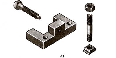
Let's look at the essence of the detailing process using the example of the "Upor" assembly unit. It will become clear if we compare the 2 drawings.
In the first drawing we see an assembly drawing and a visual image of the product, in the other - this product is divided into separate parts and working drawings of two parts are made. Let's take a closer look at these images. (Students look at the drawings)
Problematic situation.
According to the specification, we see that the assembly unit consists of 5 parts. Name them (body, block, screw, stud, nut) Why are the drawings made for only 2 parts?
A minute to think about it. Your versions!
(Children must determine that the image does not contain drawings for the elements of fastening connections - a screw, a stud and a nut, but their drawings and other data, as we know from previous lessons, are in special mechanical engineering reference books, because these are STANDARD parts)
Conclusion:Working drawings are not prepared for standard parts.
To facilitate the work of drawing up drawings, it is recommended to do this in this order:

Read the product drawing in the previously studied sequence, paying special attention to the shape of the parts, their purpose and interaction.
Mentally disassemble the product into individual parts.
Highlight standardized parts that do not have drawings.
Determine the number of images needed when drawing each part. However, you cannot copy it from the drawing to be detailed.
(Children themselves must answer that the number of views in the drawing should be MINIMUM, but SUFFICIENT for manufacturing the part. To reduce the number of images, there are various conventions, signs, and you can also use sections, sections. For example, cylindrical surfaces can be depicted with 1 view in combination with a section , and the assembly drawing contains 2 or 3 views and all views have this element.In the drawings under consideration, the part is a cracker, which is made in frontal and profile views, and when making a working drawing, the part is shown in a frontal section and horizontal view. If students find it difficult to draw such a conclusion, the teacher helps)
Find the mating surfaces of the parts, i.e. surfaces that interact with the surfaces of other parts (for example, in key joints there is a key and a keyway on the shaft). It is imperative to use reference books, especially if you have encountered a detail for the first time, or have forgotten something. This helps to unload your memory from the abundance of information, speeds up work, or, conversely, gives you more information.

For example, in the specification of the assembly drawing there was the designation: “Cotter pin 1.5 x 15 GOST 397-79.” You don't know what shape the part is or what the numbers on the entry mean. From the reference book we learn that the part has this shape. The designation should be understood as follows: cotter pin for holes with a diameter of d = 1.5 mm, cotter pin length 15 mm.
Detailing of each part must be done on separate sheets. Their format depends on the scale.
The title block must be filled out using the specification data.
5. Practical work (together with the teacher)
The figure shows a visual representation of the crank. The crank transmits motion from the connecting rod to the shaft, converting the translational movement of the piston into rotational movement of the shaft.

Crank operation diagram

The figure below shows a drawing of the crank. It is an eccentrically located finger (item 2), connected through a shoulder (item 1) to a shaft (item 3), to which rotational motion is imparted. A connecting rod coming from the piston is pivotally connected to the crank pin.
Reading the drawing
After reading the drawing, we establish according to the specification that it shows a crank. The main view and section are given. The main view contains a local section. Detail image 3 also contains a local section.
Part 6 - the bolt has a head in the form of a hexagonal prism. The main dimensions of the bolt: MB thread, rod length 25 mm. We learn this from the specification. Knowing the standard number, you can determine the “key size” (it is 10 mm), head height (4 mm) and other dimensions.
Part 5 - threaded nut MB has the shape of a hexagonal prism.
Part 2 is called “finger”. It consists of three cylinders and a truncated cone. The conical end of part 2 is riveted, which ensures the immobility of the connection with part 1.

The key (item 4) is prismatic. The height and width of the key are 6 mm, length 14 mm. We also learn this from the specification.
The “arm” part has four holes: one conical, the second cylindrical for a shaft with a diameter of 21 mm, and two also cylindrical for a MB bolt. The bolt and nut serve to tighten the arms of the arm, which clamps the shaft. Parts / and 3 are connected with a parallel key.
Sizes diameter 16 and 24 are connecting, size 160 is overall.
There is no need to draw up drawings for parts 4, 5 and 6, since they are standardized.
Execution of drawings
 The “Finger” part is made in one form, since its shape is completely revealed, although in the assembly drawing it is shown in 2 projections.
The next detail is “Shoulder”. The drawing is shown below. Note. Dimensions appeared on it that were not indicated on the assembly drawing. They are defined using an angular scale. We will study how this is done in the following lessons.
The “Shaft” part is not performed, since its shape is well known, and the dimensions of the keyway 6 and 2.8 mm that it contains are taken from the reference table
The dimensions of the mating surfaces (for diameters 16 and 21) are mutually consistent.

Detailing completed.
6. Homework:
Read the textbook material on pp. 195-198
Make out verbally the detailing in Fig. 237, 238
A creative task, at the request and choice of students, is to create a crossword puzzle or rebus with the keyword “Detailing”
The teacher gives a general description of the learning activities in the lesson; at the same time, informs them about the achievement of the lesson goals, identified shortcomings and ways to eliminate them;
objectively evaluates the results of collective and individual work and recognizes the best.
Reflection:
Today I invite you to evaluate your condition after the lesson according to the schedule.

8. In a free minute - watch a video(link in lesson equipment) if you have the necessary equipment
Application
№1 Assembly drawing and visual representation of the “Stop”

No. 2. Individual parts of the “Upor” and drawings of parts 
No. 3. Cotter pin
No. 4 Crank
No. 5. Assembly drawing of the crank
No. 6 Scheme of crank operation
No. 8 Part drawing 2 cranks
Drawing. Lesson 28 (second year of study, 9th grade). 1. Topic “Reading assembly drawings. Practical work 8" 2. Nadezhda Semenovna Gordovaya, drawing teacher at the Vydrinskaya secondary school, Kabansky district, Republic of Buryatia 3. Subject: drawing. 4.Presentation of Microsoft PowerPoint 5.Microsoft PowerPoint, Internet Explorer, own developments, didactic material, textbook by I.A. Roitman, Ya.V. Vladimirov, demonstration models, tables. 6.During drawing lessons 7.For 9th grade students 8.Volume: 14 slides, 515 Kb.
Express survey 1. What is shown on assembly drawings: an image of a part or an assembly unit? Assembly unit 2. What are assembly drawings for? To assemble an assembly unit from individual parts 3. Are sections and sections used when making assembly drawings? Apply 4.Where on the drawings are the names of the parts included in the product indicated? The table contains specifications 5. Is it necessary to include all the dimensions of the parts included in the product on the assembly drawings? No. Only dimensional, connecting, installation 6. What do the numbers on the shelves of leader lines mean? Part numbers on the drawing 7. How to hatch three touching parts on assembly drawings? In different directions, with a change in the distance between the hatching lines 8. How can a section show narrow cross-sectional areas, the width of which in the drawing is 2 mm or less? Shown in black 9. Remember what it means to “read the working drawing of a part”? Imagine its three-dimensional shape, dimensions, location of all its elements. Evaluation of results: (9, 8 correct answers – “5”, 6.7 correct answers – “4”, 4.5 correct answers – “3”)


Comparative and comparative characteristics: Working drawing Assembly drawing Made according to ESKD standards (formats, title block, lines, fonts, etc.) Images are used (views, sections, sections), conventions and simplifications An image of a part is given An image of an assembly unit is given Used for the manufacture of a part Serves for assembling a product from parts All dimensions are indicated Dimensional, connecting, installation Position numbers are indicated Availability of a table with data - specifications

Reading a drawing of a part means: using the flat images on the drawing of the part, imagine its three-dimensional shape, design, dimensions, location of all its elements. Reading an assembly drawing means: using flat images of an assembly unit, imagine its three-dimensional structure, the shape and dimensions of its individual parts, their location and connection, as well as the principle of operation of the product.


Procedure for reading assembly drawings. Find the product name. Determine which images (types, sections, sections) are given in the drawing. Using the specification, consider the images of each part and determine their geometric shape. Determine how the parts are connected to each other. Find other data given on the drawing (dimensions, technical requirements, etc.).

Conclusion: Products are assembled using assembly drawings; in addition, using assembly drawings one gets acquainted with the design of products, their principle of operation, and also, using assembly drawings, products are adjusted during operation, installed (mounted) at the workplace, and the product is repaired.
18.08.2015 4689 575 Anufrieva Elena YurievnaLesson type:lesson in developing practical skills.
Lesson Objectives: formulate ideas about the algorithm for reading an assembly drawing; teach how to read simple assembly drawings; develop spatial thinking; continue to develop critical thinking, gain experience in communicative activities, and the ability to search for necessary information in various sources. continue to form positive motivation for students to study drawing, foster tolerance towards other people’s points of view, and responsibility for their actions.
Equipment:“Algorithm for reading an assembly drawing and a visual representation of an assembly unit,” test tasks, cards for group work.
Lesson plan:
1. Organizational moment.
2. Introduction to the topic of the lesson.
3. Repetition of the studied material.
4. Development of practical skills (practical work on reading assembly drawings).
5. Consolidation of educational material.
6. End of the lesson.
DURING THE CLASSES
I. Organizational moment
II. Introduction to the topic of the lesson
Teacher.Having purchased any item, we often become familiar with the operating rules of the purchased product before we begin to use it for its intended purpose. Many years ago I bought this coffee grinder and, like every owner of a new thing, I first read the instruction manual. (A coffee grinder is demonstrated, a fragment of the instructions for its operation is read, which talks about how to adjust the degree of grinding of coffee beans using a screw called “Screw - 7”). Where is this “important” screw – 7? The answer was immediately found when looking at the assembly drawing accompanying the text of the instructions.
Of course, when dealing with the simplest mechanism or design, it is often enough just to look carefully at the product to understand its structure, make adjustments or minor repairs. What if we are talking about a machine, a car, an airplane? Or, for example, about cabinet furniture, an ordinary “wall”? In these cases, you need to be able to work with an assembly drawing, you need to be able to read it.
The topic of the lesson and its main task are reported: to learn to read simple assembly drawings.
III. Repetition of learned material/ answer yes or no to the statement/
1. An assembly drawing is necessary for the manufacture of parts of an assembly unit
2. Positions, quantity, name and materials of parts included in the assembly unit - information contained in the specification
3. On the assembly drawing, the item numbers of the parts are indicated on the leader lines first, the item numbers of the non-standard parts, and after the standard ones
4. Cross-sectional shading for two adjacent parts is performed with lines of different thicknesses, different inclinations, and the distance between the lines is the same
5. Shafts, keys, bolts, studs, all non-hollow bodies, when their cutting plane runs along their center line, are called not dissected in the drawing?
6.On the assembly drawing it is allowed to place only the main view and the right view using the necessary local sections, observing the projection relationship
7.List the name of the sizes in the order of the definitions you read
· Dimensions defining the maximum external or internal contours of the product
· Dimensions according to which the product is mounted at the installation site
· Dimensions by which the product is attached to other products
Dimensional, installation, connecting.
8. A sketch is no different from a working drawing;
9. The sketch of the part is done invisual scale;
10. The working drawing of the part must containthe maximum possible number of species;
11. On working drawings, parts withThe dimensions necessary for the manufacture and control of the manufacture of the part are entered.
12. The specification indicates the weight of the parts.
13. Are simplifications used in assembly drawings?
14. For all parts included in the assembly unit, item numbers are applied.
15. On assembly drawings put in all sizes;
16. The number of images of the part on the assembly drawing must correspond to the number of images of the part on the working drawing.
17. The specification is carried out on A4 format.
18. Images of sections of parts with a thickness or diameter of 2 mm or less are blackened;
19. Drawings containing images and data for the manufacture of parts are called assembly drawings.
20. Connections that are repeatedly found in the mechanisms of various machines are called standard.
10-14 – “3” 15-18 – “4” 19-20 – “5”
IV. Formation of practical skills
A) Familiarizing students with the algorithm for reading an assembly drawing and a visual image of an assembly unit (using a table made on paper or a presentation slide).
Algorithm for reading an assembly drawing and a visual representation of an assembly unit:
1. Determine the name of the product.
2. Set the number of parts names and their quantity.
3. Determine the image scale.
4. Analyze the number and nature of images in a drawing or a visual representation of an assembly unit.
5. Determine the outline of each part of the assembly unit in all images of the drawing.
6. Analyze the geometric shape of each part.
7. Determine the types of connections of parts in this assembly unit.
8. Analyze and set the size type.
9. Identify conventions and simplifications used in an assembly drawing or in a visual representation of an assembly unit.
10. Establish the assembly sequence of the product.
V. Consolidation and determination of the degree of students’ assimilation of educational material
Work according to the textbook Fig. 6.10 and 6.11 pp.80-81
VI. End of lesson
1) Summing up the lesson. Giving students grades for their work in class.
2) Explanation of homework: § 6.1-6.4 On A4 format, draw a frontal section, highlighting with shading where necessary the details of the assembly unit.
Download material
See the downloadable file for the full text of the material.
The page contains only a fragment of the material.
Lesson developed by teacher
Gorlovka General Educational
wcolaI – II No. 35
Dushkina I. A.
Lesson #18 (No. 4 in topic No. 13 “Reading and detailing assembly drawings”)
Date of …………
Class 9
Subject: practical work on the topic “Reading assembly drawings for
plan"
Lesson objectives:
Educational: test the knowledge, skills and abilities of students in reading assembly drawings according to the given plan, consolidate the skills of reading assembly drawings and writing notes in a drawing font.
Educational: promote diligence, accuracy, and work culture.
Developmental: promote further development of memory, attention, eye; logical, analytical and spatial thinking.
Teaching aids, drawing tools, accessories and materials.
For the teacher:
textbook “Drawing.8 – 9kl.” edited by VC. Sidorenko
educational tables containing images of assembly drawings of simple assembly units, writing a drawing font
didactic materials (cards - assignments) edited by E.A. Vasilenko
table "Reflection"
electronic version of tables, cards (if necessary equipment is available)
For students: A4 format, checkered, task cards, drawing cards
accessories and tools.
Lesson type: control and correction of knowledge, skills and abilities
During the classes
1. Organizational stage:
Greetings
Organizing the students' workplace, issuing task cards, drawing tools, accessories and materials from the office fund for work in this lesson. Checking readiness for the lesson.
Checking student attendance.
Teacher filling out a class log
Announcing the topic of the lesson.
2.Updating basic knowledge and checking homework.
The teacher visually checks homework completion
3. Motivation for learning activities.
Today we are testing your knowledge, skills and abilities in reading assembly drawings, taking into account the learned conventions and simplifications that you received in previous classes and in self-preparation for practical work. I hope that this will allow me to successfully complete today’s practical work and begin studying the topic “Detailing Assembly Drawings” in the next lesson.
Declaring the goals and objectives of the lesson:
Today in class:
Students must independently read the assembly drawing according to the given plan.
Complete a technical drawing of the part specified in the task card
Identify deficiencies and gaps in knowledge in order to correct and fill them in home preparation for subsequent lessons
At the same time, we must be attentive, think, analyze, imagine and not waste time
Good luck in your work
4. Practical work. Formation of skills and abilities.
4.1. Issuance of individual cards - tasks 10 options (attached)
4.2. Answers to questions about the assignment, if any.
4.3. Independent work of students under the visual supervision of the teacher.
5. Summing up the lesson.
The teacher gives a general description of the learning activities in the lesson;
Collects works
Reflection: continue the sentence:
I didn't think that...
I will definitely…….
It seemed to me that…….
I did not like………
I think I will need………
6. Homework:
Repeat the material on the topic “Reading assembly drawings”
At the request of students, complete a creative task on the studied section (prepare an electronic presentation, make a crossword puzzle, rebus - optional)
Application
Option #1
Exercise 1.
Task 2.
Option No. 2
Exercise 1. Read the assembly drawing according to the given plan.
Task 2. Complete technical drawing of part 1.

Option No. 3
Exercise 1. Read the assembly drawing according to the given plan.
Task 2. Complete technical drawing of part 1.

Option No. 4
Exercise 1. Read the assembly drawing according to the given plan.
Task 2. Complete technical drawing of part 1.

Option No. 5
Exercise 1. Read the assembly drawing according to the given plan.
Task 2 . Complete technical drawing of part 3.

Option No. 6
Exercise 1. Read the assembly drawing according to the given plan.
Task 2. Complete technical drawing of part 1.

Option No. 7
Exercise 1. Read the assembly drawing according to the given plan.
Task 2.

Option No. 8
Exercise 1. Read the assembly drawing according to the given plan.
Task 2. Complete technical drawing of part 8.

Option No. 9
Exercise 1. Read the assembly drawing according to the given plan.
Task 2. Complete technical drawing of part 2.

Option No. 10
Exercise 1. Read the assembly drawing according to the given plan.
Task 2. Complete technical drawing of part 1.

Extreme or intermediate position of a part. In Figure 232, the image of the pusher is continued upward by a thin line with two dots. What does this mean?
The pusher moves up and returns back to its original position. On assembly drawings, the extreme or intermediate position of a part is shown as a dot-dash line with two dots, a thin line.
Please note that in view A (see Fig. 232) the handle (part 2) is not shown. The shape of this part is determined from other images. In this view, it would cover part of the handle, which has a threaded hole. In such cases, the part is not shown, and the inscription is made on the drawing: “Handle (part 2) not shown.”
Illustration of border details. Sometimes an assembly drawing needs to show parts that are not included in the product. Part of such a part is shown in Figure 248. It is outlined with a thin line. This makes it possible to distinguish it from parts included directly in the product.
Picture of sealing devices. To prevent the leakage of liquid, steam or air between the moving parts of various taps, valves and pipelines, sealing devices are used.
One of them is a stuffing box device (Fig. 242). For the sealing packing, it uses salted hemp, compressed using a pressure sleeve. The bushing (indicated by an arrow with the number 1) is connected to the body of the part with a thread. By tightening the bushing, you can compress the packing so that it fits tightly against the cylindrical axis. In the drawing, the packing (it is indicated by an arrow with the number 2) is shaded in a cage as a non-metallic material (see Fig. 198).
Rice. 242. Stuffing box device
When drawing stuffing box devices, the pressure sleeve is always shown in the extended (original) position.
Reduce the number and size of images. In assembly drawings, as in detail drawings, to reduce the number of images, you can combine half the view with half the section (Fig. 242 and 243). You can also connect part of a view to part of a section view.

Rice. 243. Conventional image of repeating elements
To reduce the size of the image without reducing the scale, a cut is used (see Fig. 242, top view).
Image of identical elements. Instead of several identical elements, it is allowed to depict only one of them on assembly drawings. So, for example, in Figure 243 only one bolt with a nut is shown (parts 3 and 4). The position of the others is shown by the intersection of the center lines. And in Figure 242 only one of four identical bolt holes is shown.
- Which line shows the extreme or intermediate position of a part on assembly drawings? When is this image used?
- How to understand the inscription on the assembly drawing: “Handle (part 2) not shown”?
- When on an assembly drawing is a part outlined not with a main line, but with a thin line? What does it mean?
- How can the number of images on an assembly drawing be reduced if it is necessary to show both the external view and the internal structure of the product?
Practical work No. 18. Reading assembly drawings
- Figures 244-248 show assembly drawings of five different products, and Figure 249 shows visual representations of six products. Some of them are given in figures 244-248, but not all. Determine which visual images, indicated by letters, show exactly those products that are also contained in the assembly drawings. Write down in your workbook which of the visual images shows which product. Recording form: “On the visual image A is drawn...” (take the name of the product from the assembly drawing).
Do not forget that not all assembly drawings include visual images.
- Read the assembly drawings indicated by the teacher in Figures 244-248, following the sequence given in 35. Answer questions (including additional ones) in writing.
Additional questions regarding assembly drawings

Rice. 244. Reading drawing
To Figure 244
- Why is detail 37 not shaded?
- Why is item 2 cross-shaded?

Rice. 245. Reading drawing
To Figure 245
- Is image B-B a section or a section?
- What is it given for?

Rice. 246. Reading drawing
To Figure 246
- Why was incision A - A made?
- What is the shape of part 5?

Rice. 247. Reading drawing
To Figure 247
- Why is item 3 cross-shaded?
- Why do the shading of parts 1 and 2 have different directions?

Rice. 248. Reading drawing
To Figure 248
- Which line represents the workpiece being processed?
- Why is the special screw (part 3) not shaded on section A - A, but shaded on section B - B?

Rice. 249 Exercise task
Purpose and arrangement of assembly units included in practical work No. 19.
- The handle (Fig. 244) is attached to the door leaf using screws, for which holes are provided on the base (part 1). The handle consists of a base and a handle connected with a screw (part 3).
- Puller (Fig. 245) - a device for removing pulleys, bearings and other parts from shafts.
The main parts of the puller: the rocker arm (part 1), on which the grips (part 3) and the pressure screw (part 2) are attached. A limiter (part 4) secured with screws (part 5) prevents the grip from slipping off the rocker arm.
The device to be dismantled is installed on the protrusions of the grippers. The removal of parts is carried out by rotating the pressure screw, into the hole of which a rod (lever) is inserted for this purpose.
- Device (Fig. 246) - a jig is used when drilling holes on tiles, in this case having a rectangular protrusion.
The base (part 1) of the conductor is connected to the plate (part 2) with pins (part 5) and screws (part 6). There is a guide bushing (part 3) on top of the plate, and a handle (part 4) is screwed into the side.
When drilling a hole, the protrusion of the workpiece is inserted into a rectangular hole in the base, the drill is guided through the sleeve from above.
- The roller (Fig. 247) serves as a support for moving heavy objects. It is used in sets of several pieces. The roller (part. 2) with a rubber tire (part. 3) is attached to the base (part. /) using a bolt (part. 4) and a nut (part. 5) with a washer (part. c).
- The invoice jig (Fig. 248) is used when drilling, in this case, two holes with a diameter of 4.2 in the workpiece. The screw (part 3) of the jig is attached to the drilling machine table. After installing the workpiece, a plate (part 1) is placed on it, which is secured with a hook (part 4). The hook provides easy and quick fastening of the conductor plate.