External forces- these are forces acting on a body from the outside. Under the influence of external forces, a body either begins to move if it was at rest, or the speed of its movement or the direction of movement changes. External forces in most cases are balanced by other forces and their influence is invisible.
External forces acting on a solid body cause changes in its shape, caused by the movement of particles.
External forces:
- gravity - this is the force that acts on a body in the field of gravity. On the surface of the earth, the force of gravity is equal to the mass of the body. It is always directed vertically downwards, perpendicular to the horizon. The point of application is the general center of gravity of the body.
-ground reaction force - this is the force acting on the body from the side of the support when there is pressure on it.
-friction force - this is the force that occurs during contact between bodies and during the movement of the body.
-environmental resistance force- a force that arises when a body moves in an air or water environment.
-inertial force - a force that occurs when a body moves with acceleration.
By internal forces are the forces acting between particles, these forces resist changing shape.
Internal forces are divided into active and passive.
Active forces include the force of contraction of skeletal muscles.
Muscle strength is determined by:
Physiological diameter,
Area of origin and attachment,
The type of lever in which the movement occurs.
Passive ones include: the force of elastic traction of soft tissues, the resistance force of cartilage, bones, the force of molecular adhesion of synovial fluid.
The concept of the general center of gravity of the body and the area of support. Their meaning.
GCT is composed of centers of gravity of individual parts of the body, and partial centers of gravity. It plays an important role in solving problems of mechanics of movement. It is one of the indicators of physique.
Support area- the area enclosed between the outer borders of the right and left foot. The size of the support area varies depending on the position of the body.
Types of body balance. The degree of stability of the body, its definition and meaning.
There are three types: stable (when the body’s central gravity is disturbed, the body’s central gravity increases and hangs on the crossbar), unstable (the central gravity of the body decreases), and indifferent (the central gravity of the body is constant).
The degree of stability depends on the height of the GBC and the size of the support area. The larger the support area and the lower the GBC, the higher the degree of stability.
The quantitative expression is the stability angle. This is the angle formed vertically by gravity and a tangent drawn to the edge of the support.
Characteristics of the athlete's movements. Types of movements. Examples.
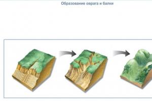
Weathering itself does not lead to the formation of relief forms, but only turns hard rocks into loose ones and prepares the material for movement. The result of this movement is various forms of relief.
Effect of gravity
Under the influence of gravity, destroyed rocks move on the surface of the Earth from elevated areas to lower ones. Blocks of stone, crushed stone, and sand often rush down steep mountain slopes, causing landslides and screes.
Under the influence of gravity there are landslides and mudflows. They carry huge masses of rocks. Landslides are the sliding of rock masses down a slope. They form along the banks of reservoirs, on the slopes of hills and mountains after heavy rains or melting snow. The upper loose layer of rocks becomes heavier when saturated with water and slides down the lower, water-impervious layer. Heavy rains and rapid snow melting also cause mudflows in the mountains. They move down the slope with destructive force, demolishing everything in their path. Landslides and mudflows lead to accidents and loss of life.
Activity of flowing waters
The most important transformer of relief is moving water, which performs great destructive and creative work. Rivers cut wide river valleys on the plains and deep canyons and gorges in the mountains. Small water flows create gully-gully relief on the plains.
Flowing bottoms not only create depressions on the surface, but also capture rock fragments, transport them and deposit them in depressions or their own valleys. This is how flat plains are formed from river sediments along rivers

Karst
In those areas where easily soluble rocks (limestone, gypsum, chalk, rock salt) lie close to the earth's surface, amazing natural phenomena are observed. Rivers and streams, dissolving rocks, disappear from the surface and rush deep into the bowels of the earth. Phenomena associated with the dissolution of surface rocks are called karst. The dissolution of rocks leads to the formation of karst landforms: caves, abysses, mines, funnels, sometimes filled with water. Beautiful stalactites (multi-meter calcareous “icicles”) and stalagmites (“columns” of limestone growths) form bizarre sculptures in the caves.
Wind activity
In open treeless spaces, the wind moves giant accumulations of sand or clay particles, creating aeolian landforms (Aeolus is the patron god of the wind in ancient Greek mythology). Most of the sandy ones are covered with dunes and sandy hills. Sometimes they reach a height of 100 meters. From above the dune has the shape of a sickle.
Moving at high speed, particles of sand and crushed stone process stone blocks like sandpaper. This process goes faster at the surface of the earth, where there are more grains of sand.
As a result of wind activity, dense deposits of dust particles can accumulate.
Such homogeneous, porous, grayish-yellow rocks are called loess.
Glacier activity
Human activity
Humans play a major role in changing the relief. The plains are especially strongly changed by its activities. People have been settling on the plains for a long time; they build houses and roads, fill up ravines, and construct embankments. Man changes the relief during mining: huge quarries are dug, heaps of heaps are piled up - dumps of waste rock.
The scale of human activity can be comparable to natural processes. For example, rivers carve out their valleys, carrying out rocks, and humans build canals of comparable size.
Landforms created by humans are called anthropogenic. Anthropogenic changes in relief occur with the help of modern technology and at a fairly rapid pace.
Moving water and wind perform enormous destructive work, which is called (from the Latin word erosio, corroding). Land erosion is a natural process. However, it intensifies as a result of human economic activity: plowing slopes, deforestation, excessive grazing, and building roads. In the last hundred years alone, a third of all the world's cultivated land has been eroded. These processes reached their greatest extent in large agricultural regions of Russia, China and the USA.
Formation of the Earth's relief
Features of the Earth's relief
Mechanical system is a collection of material points or bodies in which the position or movement of each point or body depends on the position and movement of all the others. So, for example, when studying the movement of the Earth and the Moon relative to the Sun, the totality of the Earth and the Moon is a mechanical system consisting of two material points; when a projectile breaks into fragments, we consider the fragments as a mechanical system. A mechanical system is any mechanism or machine.
If the distances between points of a mechanical system do not change when the system is moving or at rest, then such a mechanical system is called immutable.
The concept of an unchangeable mechanical system makes it possible to study the arbitrary motion of solid bodies in dynamics. In this case, as in statics and kinematics, by a rigid body we will understand a material body in which the distance between each two points does not change when the body moves or rests. Any solid body can be mentally divided into a sufficiently large number of sufficiently small parts, the totality of which can be approximately considered as a mechanical system. Since a solid body forms a continuous extension, in order to establish its exact (and not approximate) properties it is necessary to make a limiting transition, the ultimate fragmentation of the body, when the sizes of the considered parts of the body simultaneously tend to zero.
Thus, knowledge of the laws of motion of mechanical systems allows us to study the laws of arbitrary motion of solid bodies.
All forces acting on points of a mechanical system are divided into external and internal forces.
External forces in relation to a given mechanical system are forces acting on points of this system from material points or bodies not included in the system. Designations: - external force applied to the th point; ![]() -the main vector of external forces;
-the main vector of external forces; ![]() - the main moment of external forces relative to the pole.
- the main moment of external forces relative to the pole.
Internal forces are the forces with which material points or bodies included in a given mechanical system act on points or bodies of the same system. In other words, internal forces are the forces of interaction between points or bodies of a given mechanical system. Designations: - internal force applied to the th point; ![]() -the main vector of internal forces;
-the main vector of internal forces; ![]() - the main moment of internal forces relative to the pole.
- the main moment of internal forces relative to the pole.
3.2 Properties of internal forces.
First property.The main vector of all internal forces of a mechanical system is equal to zero, that is
![]() . (3.1)
. (3.1)
Second property.The main moment of all internal forces of a mechanical system relative to any pole or axis is equal to zero, that is
![]() ,
, ![]() . (3.2)
. (3.2)
|
 To prove these properties, we note that since internal forces are the forces of interaction of material points included in the system, then according to Newton’s third law, any two points of the system (Fig. 17) act on each other with forces and equal in magnitude and opposite towards.
 Thus, for each internal force there is a directly opposite internal force and, therefore, the internal forces form a certain set of pairwise opposite forces. But the geometric sum of two directly opposite forces is zero, so
![]() .
.
As was shown in statics, the geometric sum of the moments of two directly opposite forces relative to the same pole is equal to zero, therefore
![]() .
.
A similar result is obtained when calculating the main moment about the axis
![]() .
.
3.3 Differential equations of motion of a mechanical system.
Let us consider a mechanical system consisting of material points whose masses are . For each point we apply the basic equation of point dynamics
![]() ,
, ![]() ,
,
![]() , (3.3)
, (3.3)
de is the resultant of external forces applied to the th point, and is the resultant of internal forces.
The system of differential equations (3.3) is called differential equations of motion of a mechanical system in vector form.
Projecting vector equations (3.3) onto rectangular Cartesian coordinate axes we obtain differential equations of motion of a mechanical system in coordinate form:
![]() ,
,
![]() , (3.4)
, (3.4)
![]() ,
,
![]() .
.
These equations are a system of second-order ordinary differential equations. Consequently, to find the motion of a mechanical system according to given forces and initial conditions for each point of this system, it is necessary to integrate a system of differential equations. Integrating the system of differential equations (3.4), generally speaking, is associated with significant, often insurmountable, mathematical difficulties. However, in theoretical mechanics, methods have been developed that make it possible to circumvent the main difficulties that arise when using differential equations of motion of a mechanical system in the form (3.3) or (3.4). These include methods that provide general theorems for the dynamics of a mechanical system, establishing the laws of change in some total (integral) characteristics of the system as a whole, and not the patterns of movement of its individual elements. These are the so-called measures of motion - the main vector of momentum; principal moment of momentum; kinetic energy. Knowing the nature of the change in these quantities, it is possible to form a partial, and sometimes complete, picture of the movement of a mechanical system.
IV. BASIC (GENERAL) THEOREMS OF DYNAMICS OF A POINT AND SYSTEM
 4.1 Theorem on the motion of the center of mass.
4.1.1. Center of mass of a mechanical system.
Let us consider a mechanical system consisting of material points whose masses are .
The mass of the mechanical system, consisting of material points, we will call the sum of the masses of the points of the system:
Definition. The center of mass of a mechanical system is a geometric point, the radius vector of which is determined by the formula:
where is the radius vector of the center of mass; -radius vectors of system points; -their masses (Fig. 18).
 ;
;  ; . (4.1")
The center of mass is not a material point, but geometric. It may not coincide with any material point of the mechanical system. In a uniform gravity field, the center of mass coincides with the center of gravity. This does not mean, however, that the concepts of center of mass and center of gravity are the same. The concept of the center of mass is applicable to any mechanical systems, and the concept of the center of gravity is applicable only to mechanical systems that are under the influence of gravity (that is, attraction to the Earth). So, for example, in celestial mechanics, when considering the problem of the motion of two bodies, for example the Earth and the Moon, one can consider the center of mass of this system, but one cannot consider the center of gravity.
Thus, the concept of center of mass is broader than the concept of center of gravity.
4.1.2. Theorem on the motion of the center of mass of a mechanical system.
Theorem. The center of mass of a mechanical system moves as a material point, the mass of which is equal to the mass of the entire system and to which all external forces acting on the system are applied, that is
![]() .
(4.2)
.
(4.2)
Here ![]() -the main vector of external forces.
-the main vector of external forces.
Proof. Let's consider a mechanical system, the material points of which move under the influence of external and internal forces. is the resultant of external forces applied to the th point, and is the resultant of internal forces. According to (3.3), the equation of motion of the th point has the form
![]() ,
, ![]() .
.
Adding the left and right sides of these equations, we get
![]() .
.
Since the main vector of internal forces is equal to zero (section 3.2, first property), then
![]() .
.
Let's transform the left side of this equality. From formula (4.1), which determines the radius vector of the center of mass, it follows:
![]() .
.
Throughout the following we will assume that only mechanical systems of constant composition are considered, that is, and . Let us take the second derivative with respect to time from both sides of this equality
![]()
Because ![]() , -
acceleration of the center of mass of the system, then, finally,
, -
acceleration of the center of mass of the system, then, finally,
![]() .
.
Projecting both sides of this vector equality onto the coordinate axes, we obtain:
![]() ,
,
![]() , (4.3)
, (4.3)
![]() ,
,
where , , are projections of force;
Projections of the main vector of external forces on the coordinate axes.
Equations (4.3)- differential equations of motion of the center of mass of a mechanical system in projections onto Cartesian coordinate axes.
From equations (4.2) and (4.3) it follows that Internal forces alone cannot change the nature of the movement of the center of mass of a mechanical system. Internal forces can have an indirect effect on the movement of the center of mass only through external forces. For example, in a car, the internal forces developed by the engine influence the movement of the center of mass through the friction forces of the wheels and the road.
4.1.3. Laws of conservation of motion of the center of mass
(corollaries from the theorem).
From the theorem on the motion of the center of mass, the following corollaries can be obtained.
Corollary 1.If the main vector of external forces acting on the system is zero, then its center of mass is at rest or moves rectilinearly and uniformly.
Indeed, if the main vector of external forces is , then from equation (4.2):
If, in particular, the initial velocity of the center of mass is , then the center of mass is at rest. If the initial speed is , then the center of mass moves rectilinearly and uniformly.
Corollary 2.If the projection of the main vector of external forces onto any fixed axis is zero, then the projection of the velocity of the center of mass of the mechanical system onto this axis does not change.
This consequence follows from equations (4.3). Let, for example, then
![]() ,
,
from here. If at the initial moment , then:
that is, the projection of the center of mass of the mechanical system onto the axis in this case will not move along the axis. If , then the projection of the center of mass onto the axis moves uniformly.
4.2 The amount of motion of a point and a system.
 Theorem on the change of momentum.
4.2.1. The amount of motion of a point and a system.
Definition. The quantity of motion of a material point is a vector equal to the product of the mass of the point and its speed, that is
. (4.5)
Vector collinear to the vector and directed tangentially to the trajectory of the material point (Fig. 19).
The momentum of a point in physics is often called impulse of a material point.
The dimension of momentum in SI-kg·m/s or N·s.
Definition. The quantity of motion of a mechanical system is a vector equal to the vector sum of the quantities of movements (the main vector of the quantities of movements) of individual points included in the system, that is
![]() (4.6)
(4.6)
Projections of momentum onto rectangular Cartesian coordinate axes:
Momentum vector of the system unlike the momentum vector of a point, it does not have a point of application. The momentum vector of a point is applied at the most moving point, and the vector is a free vector.
Lemma of quantities of motion. The momentum of a mechanical system is equal to the mass of the entire system multiplied by the speed of its center of mass, that is
Proof. From formula (4.1), which determines the radius vector of the center of mass, it follows:
![]() .
.
Let us take the time derivative of both sides
![]() , or
, or ![]() .
.

 From here we get
, which was what needed to be proven.
From here we get
, which was what needed to be proven.
From formula (4.8) it is clear that if a body moves in such a way that its center of mass remains motionless, then the momentum of the body is zero. For example, the amount of motion of a body rotating around a fixed axis passing through its center of mass (Fig. 20),
, because
If the motion of the body is plane-parallel, then the amount of motion will not characterize the rotational part of the motion around the center of mass. For example, for a wheel that is rolling (Fig. 21), regardless of how the wheel rotates around the center of mass. The amount of motion characterizes only the translational part of the movement together with the center of mass.
4.2.2. Theorem on the change in momentum of a mechanical system
in differential form.
Theorem.The time derivative of the momentum of a mechanical system is equal to the geometric sum (principal vector) of external forces acting on this system, i.e.
![]() .
(4.9)
.
(4.9)
Proof. Let us consider a mechanical system consisting of material points whose masses are ; ![]() -resultant of external forces applied to the th point. In accordance with the momentum lemma, formula (4.8):
-resultant of external forces applied to the th point. In accordance with the momentum lemma, formula (4.8):
Let us take the derivative with respect to time from both sides of this equality
![]() .
.
The right side of this equality from the theorem on the motion of the center of mass is formula (4.2):
![]() .
.
Finally:
![]()
and the theorem is proven .
In projections onto rectangular Cartesian coordinate axes:
![]() ;
;  ;
; ![]() , (4.10)
, (4.10)
that is the time derivative of the projection of the momentum of a mechanical system onto any coordinate axis is equal to the sum of the projections (projection of the main vector) of all external forces of the system onto the same axis.
4.2.3. Laws of conservation of momentum
(corollaries from the theorem)
Corollary 1.If the main vector of all external forces of a mechanical system is equal to zero, then the amount of motion of the system is constant in magnitude and direction.
Indeed, if ![]() ,
then from the theorem on the change in momentum, i.e. from equality (4.9) it follows that
,
then from the theorem on the change in momentum, i.e. from equality (4.9) it follows that
Corollary 2.If the projection of the main vector of all external forces of a mechanical system onto a certain fixed axis is equal to zero, then the projection of the momentum of the system onto this axis remains constant.
Let the projection of the main vector of all external forces onto the axis be equal to zero: ![]() . Then from the first equality (4.10):
. Then from the first equality (4.10):
4.2.4. Theorem on the change in momentum of a mechanical system
in an integral form.
An elementary impulse of force is called a vector quantity equal to the product of the force vector and an elementary time interval
. (4.11)
The direction of the elementary impulse coincides with the direction of the force vector.
Force impulse over a finite period of time equal to a certain integral of the elementary momentum
![]() . (4.12)
. (4.12)
If the force is constant in magnitude and direction (), then its impulse over time equal to:
Projections of the force impulse on the coordinate axes:
Let us prove the theorem about the change in momentum of a mechanical system in integral form.
Theorem.The change in the momentum of a mechanical system over a certain period of time is equal to the geometric sum of the impulses of the external forces of the system over the same period of time, i.e.
![]() (4.14)
(4.14)
Proof. Let at the moment of time the amount of motion of the mechanical system be equal, and at the moment of time -; -impulse of an external force acting on the th point in time.
We use the theorem on the change in momentum in differential form - equality (4.9):
![]() .
.
Multiplying both sides of this equality by and integrating over the range from to , we obtain
![]() ,
, ![]() ,
, ![]() .
.
The theorem on the change in momentum in integral form has been proven.
In projections on the coordinate axes according to (4.14):
![]() ,
,
![]() , (4.15)
, (4.15)
![]() .
.
4.3. Theorem on the change in angular momentum.
4.3.1. Kinetic moment of a point and a system.
In statics, the concepts of moments of force relative to the pole and axis were introduced and widely used. Since the momentum of a material point is a vector, it is possible to determine its moments relative to the pole and axis in the same way as the moments of force are determined.
 Definition. relative to the pole is called the moment of its vector of momentum relative to the same pole, i.e.
. (4.16)
Momentum of a material point relative to the pole is a vector (Fig. 22) directed perpendicular to the plane containing the vector and the pole in the direction from which the vector is relative to the pole visible in a counterclockwise direction. Vector module
equal to the product of the module and the arm - the length of the perpendicular lowered from the pole on the line of action of the vector:
![]()
The angular momentum relative to the pole can be represented as a vector product: the angular momentum of a material point relative to the pole is equal to the vector product of the radius of the vector drawn from the pole to the point by the momentum vector:
![]() (4.17)
(4.17)
 Definition. Kinetic moment of a material point relatively axis is called the moment of its vector of momentum relative to the same axis, i.e.
. (4.18)
Kinetic moment of a material point relative to the axis (Fig. 23) is equal to the product of the projection of the vector taken with a plus or minus sign onto a plane perpendicular to the axis , on the shoulder of this projection:
where shoulder is the length of the perpendicular dropped from the point axis intersections with the plane on the line of action of the projection, and if, looking towards the axis , the projection relative to the point is visible directed counterclockwise, and otherwise.
The dimension of the kinetic moment in SI-kg m 2 /s, or N m s.
Definition. The kinetic moment or principal moment of momentum of a mechanical system relative to a pole is a vector equal to the geometric sum of the kinetic moments of all material points of the system relative to this pole:
![]() .
(4.19)
.
(4.19)
Definition. The kinetic moment or principal moment of momentum of a mechanical system relative to an axis is the algebraic sum of the kinetic moments of all material points of the system relative to this axis:
![]() . (4.20)
. (4.20)
The kinetic moments of a mechanical system relative to a pole and an axis passing through this pole are related by the same dependence as the main moments of a system of forces relative to the pole and axis:
-projection of the kinetic moment of a mechanical system relative to the pole onto the axis ,passing through this pole is equal to the angular momentum of the system relative to this axis, i.e.
. (4.21)
4.3.2. Theorems on the change in the kinetic moment of a mechanical system.
Let us consider a mechanical system consisting of material points whose masses are . Let's prove the theorem on the change in the angular momentum of a mechanical system relative to the pole.
Theorem.The time derivative of the kinetic moment of a mechanical system relative to a fixed pole is equal to the main moment of the external forces of the system relative to the same pole, i.e.
![]() .
(4.22)
.
(4.22)
Proof. Let us choose some fixed pole . The kinetic moment of the mechanical system relative to this pole, by definition, is equality (4.19):
![]() .
.
Let's differentiate this expression with respect to time:
Let's look at the right side of this expression. Calculating the derivative of the product:
 , (4.24)
It is taken into account here that . The vectors and have the same direction, their vector product is equal to zero, therefore, the first sum in equality (4.24).
System of material points (or tel) Any set of them that we have identified is called. Each body of the system can interact both with bodies belonging to this system and with bodies not included in it. The forces acting between the bodies of the system are called internal forces. Forces acting on bodies of a system from bodies not included in this system are called by external forces. The system is called closed (or isolated), if it includes all interacting bodies. Thus, in a closed system, only internal forces act.
Strictly speaking, closed systems do not exist in nature. However, it is almost always possible to formulate the problem in such a way that external forces can be neglected (due to their smallness or compensated™, i.e. mutual destruction) in comparison with internal ones. The choice of an imaginary surface that limits the system is the prerogative (free will) of the subject, i.e. should be carried out by the researcher based on an analysis of internal and external forces. The same system of bodies can be considered closed or open under different conditions, depending on the formulation of the problem and the given accuracy of its solution.
In a closed system of bodies, all phenomena are described using simple and general laws, therefore, if the conditions of the problem allow, then the small action of external forces should be neglected and the system should be considered as closed. This is what is often called a physical model of objective reality.
A special case of an ideal mechanical system is an absolutely solid body, which can neither deform, nor change in volume, much less be destroyed (obviously, there are no such bodies in nature): the distance between the individual material points forming such a system remains constant for all types of interaction.
Now let us introduce the very important concept in mechanics of the center of mass (center of inertia) of a system of material points. Let us take a system consisting of N material points. Center of mass of a mechanical system is called point C, the position radius vector of which in an arbitrarily chosen reference system is given by the relation:
where /u is the mass of the material point; /; - radius vector drawn from the origin of the reference system to the point where T,.
If we place the origin of coordinates at point C, then Rc= 0 and then
which leads to a different definition of the center of mass: center of mass of a mechanical system - this is a point for which the sum of the products of the masses of all material points forming a mechanical system by their radius vectors drawn from this point is the beginning of the coord
dinat are equal to zero. In Figure 1.

Rice. 1.11.
1 this is illustrated by the example of a system consisting of two bodies (for example, a diatomic molecule).
Radius vector Rc of this system the MT in the Cartesian coordinate system has coordinates X c, Y c, Z c(general three-dimensional case). In this case, the position of the center of mass can be determined by the following equations:

Where M- total mass of the mechanical MT system,
So far we have been operating with the totality N discrete material points. But what about determining the center of mass of an extended body, the mass of which is distributed continuously in space? In this case, it is natural to move from summation in (1.68)-(1.70) to integration. In this case, in vector form we get

For bodies with a plane of symmetry (as in the example) the center of mass is located in this plane. If a body has an axis of symmetry (axis X in our example), then the center of mass must certainly lie on this axis; if the body has a center of symmetry (for example, as in the case of a homogeneous ball), then this center must coincide with the position of the center of mass.

In order to determine how the center of mass of the system moves, we write expressions (1.70) in the form
=MZ C and differentiate them twice in time (all mass
we assume constant)
Comparing the obtained equalities with expressions (1.51), we obtain

or (in vector form)


These equations, called differential equations of motion of the center of mass, coincide in structure with the differential equations of motion of a material point. This allows us to formulate a theorem on the movement of the center of mass: the center of mass of a mechanical system moves as a material point, the mass of which is equal to the mass of the entire system and to which all external forces acting on the system are applied.
If the system is not acted upon by external forces, i.e. the action of external forces is compensated), then
those. the speed of movement of the center of mass of a closed system always remains constant (conserved). Internal forces do not have any effect on the movement of the center of mass of the system. If, in particular, in a given inertial coordinate system the center of mass of a closed system is at rest at one instant of time, then this means that it will always be at rest.
Many problems in mechanics are solved most simply in a coordinate system associated with the center of mass.
- With the coordinate system chosen in the example, Zc = 0 (flat one-dimensional case).
External forces are those acting on a body from points or bodies that are not part of the given body or system. Internal forces are those with which the points of a given body act on each other.
Destruction or even simple failure of a structural element is possible only with an increase in internal forces and when they pass through a certain limiting barrier. It is convenient to calculate the height of this barrier from the level that corresponds to the absence of external forces. Essentially, only additional internal forces that arise only in the presence of external forces need to be taken into account. In mechanics, these additional internal forces are simply called internal forces in the narrow, mechanical sense.
Internal forces are determined using the “method of sections”, which is based on a fairly obvious statement: if the body as a whole is in equilibrium, then any part isolated from it is also in this state
Figure 2.1.5
Let us consider a rod in equilibrium under the action of a system of external forces, Fig. 2.1.5, a. Let us mentally divide it into two parts using section AB, Fig. 2.1.5, b. To each of the sections AB of the left and right parts we will apply a system of forces corresponding to the internal forces acting in a real body, Fig. 1.7, c. Thus, using the method of sections, internal forces are converted into external forces in relation to each of the cut off parts of the body, which makes it possible to determine them from the equilibrium conditions of each of these parts separately.
Section AB can be oriented in any way, but a cross section perpendicular to the longitudinal axis of the rod turns out to be more convenient for further discussion.
Let us introduce the following notation:
main vectors and main moments of external and internal forces applied to the left cut-off part. Taking into account the introduced notation, the equilibrium conditions of this body can be written as:
0, + =0 (2.1.1)
Similar expressions can be compiled for the right cut off part of the rod. After simple transformations you can get:
=- , =- (2.1.1)
which can be interpreted as a consequence of the well-known law of mechanics: an action is always accompanied by an equal and opposite reaction.
In the case of solving the problem of dynamic action on a rod, one can turn to the well-known d’Alembert principle, according to which inertial forces are added to external forces, which again reduces the problem to equilibrium equations. Therefore, the section method procedure remains
The values and do not depend on the orientation of the section AB (see Fig. 2.1.5). However, in practical calculations it seems most convenient to use a cross section. In this case, the normal to the section coincides with the longitudinal axis of the rod. Further, the main vector and the main moment of internal forces are usually presented in the form of their projections onto orthogonal coordinate axes, with one of the axes (for example, the x axis) aligned with the mentioned normal, see Fig. 2.1.6.

Figure 2.1.6
Let us expand the vectors , , , along the coordinate axes, Fig. 2.1.6, a-d. The components of the main vector and the main moment have generally accepted names. The force N x normal to the section plane is called the normal (longitudinal) force, and Q x and Q y are called transverse (cutting) forces. Moments about the axes at And z, i.e. M y and M z will be bending and the moment relative to the longitudinal axis X, i.e. M x - torque.
The components of the main moment of internal forces in the resistance of materials are most often displayed as shown in Fig. 2.1.6, d and f.
Vector equilibrium equations can be represented as a projection onto the coordinate axes:
Thus, each component of the main vector for the main moment of internal forces is calculated as the sum of the projections of all external forces onto the corresponding axis or as the sum of the moments of all external forces relative to this axis (taking into account the accepted sign rule), located on one side of the section.
The projection of a vector onto the coordinate axis, being a scalar quantity, can be either positive or negative. This depends on whether the direction of the projection coincides with the positive or negative direction of the axis, respectively. For internal forces, this rule is observed only for the case when the normal X is external, as was the case for the left cut off part in Fig. 2.1.6. In a situation where normal X is internal, see the right cut off part in Fig. 2.1.6, the sign of the internal force is taken positive when its direction coincides with the negative direction of the axis. In Fig. 2.1.6 all projections of internal forces N x , Q x , Q y , M x , M y and M z (both those related to the left and those related to the right cut-off parts) are depicted as positive.