Surface reflectance. The weighted average reflectance of the interior surfaces of the room. transmittance.
The most important property of the surface of an object, which determines its color and brightness, is the reflectance of the surface at various frequencies: in the visible, infrared and radio ranges. Surface reflectance(p) characterizes the ability of the surface to reflect the light flux incident on it; is determined by the ratio of the luminous flux reflected from the surface to the luminous flux incident on it
The weighted average reflection coefficient of the interior surfaces of the room (p Wed ) where S st, S sweat, S floor - respectively, the area of \u200b\u200bthe walls, ceiling and floor, m 2 and P st, P sweat, P floor - respectively, the reflection coefficients of the walls, ceiling and floor.
transmittance,- the ratio of the light flux passing through the layer to the light flux incident on the layer: τ=F/F. The transmittance is a measure of the transparency of a layer. Depending on the nature of the change in the beam when passing through the layer, transmission is divided into directed, scattered, directionally scattered and mixed. It is quite obvious that the transmittance is always less than unity, since all bodies more or less absorb the light passing through them, and the greater the absorption, the thicker the layer.
3. Natural lighting keo
What is the coefficient of natural light (LKL)?
This is expressed as a percentage the ratio of natural illumination E B at any point on the working surface inside the room to the simultaneous value of the external horizontal illumination E n created by diffused light from a completely open sky. e \u003d E in / E n * 100%
KEO shows what proportion of the illumination at a given point in the room is from the simultaneous illumination of a horizontal surface in an open area with diffuse skylight
What factors affect the values of the coefficient of natural light at the calculated point of the room?
Uneven brightness of the sky
Influence of glazing of window openings
Amplification of illumination by reflected light
4. Normalization of the coefficient of natural light.
On what factors does the standard value of the coefficient of natural light depend?
In addition to the purpose of the premises (the nature of the visual work performed in the premises), when normalizing natural lighting, the light climate of the construction area (i.e. the prevailing conditions of outdoor illumination, the amount of sunlight, the stability of the snow cover) and the orientation of the light opening on the sides of the horizon are also taken into account. Because of this, the normalized value of KEO is determined by the formula

Principles of normalization of the coefficient of natural illumination.

5. Geometric keos

The principle of calculating the geometric KEO
Only the diffuse light of the sky is taken into account and the real conditions of consecration are not taken into account: unevenness, brightness of the sky, the effect of glazing of window openings, reflected light. Determined with the help of Mr. Danilyuk. when constructing the firmament, they represent it as a uniformly bright hemisphere centered at the calculated point, the luminous spherical surface of the firmament is divided into 10 4 sections, the areas of projections of which onto the horizontal surface of the base are the same. One ray leads from each section of the sky to the calculated point. Illumination at a point on the horizon. around the opening plane of the firmament E n corresponds to 10 4 rays. Inside the room E in corresponds to the number of rays N, falling through the light opening.

Calculation procedure (for the city of Danilyuk):
Draw plan and section on the same scale
Determine the position of the calculated point and plane.
On the section, connect the calculated point with the edges of the light opening through which the celestial sphere is visible
According to gr.1, determine the number of rays; for this, the calculated point is combined with the pole of the graph, the calculated plane with the horizontal axis of the face. Consider the distances between solid lines as rays. Dashed lines on the graph 1 - 10th part of the beam.
Set point C, dividing the site in half.
According to gr.1, determine the number of the semicircle passing near the point C.
On the plan (2nd graph) place the vertical axis of the graph coinciding with the characteristic calculated section.
The number of the horizontal line corresponds to the number of the semicircle, match it with the outer face.
Determine the number of rays
Calculate the geometric coefficient of daylight
The Danilyuk graph is superimposed on the cross section of the building, the center of the graph is aligned with the dot. the number of rays n1 is counted, the number of the semicircle is marked, which passes through the point C - the middle of the light opening. Schedule 2 is superimposed on the plan. Its axis coincides with the horizon and passes through point C. By the number of the semicircle, we count the number of rays passing through the light opening.
Calculated by gr. Danilyuk KEO coincides with the calculated one, if the sky is uniformly bright, there is no filling in the light opening (frames, glass, etc.), the underlying layer of the earth and the surface of the room are absolutely black.
Charts Danilyuk
Each graph contains 100 rays. Rays are numbered from the graph axis in both directions. The ray is the gap between the solid lines. Dashed lines on graph 1 are 10th parts of the beam (50). Each arc (semicircle) on gr.1 corresponds to a horizontal line (horizontal line) on graph 2. The arcs and horizontals on the graphs are numbered. Designed based on the solid angle law.
The distribution of currents and voltages in a long line is determined not only by wave parameters that characterize the line's own properties and do not depend on the properties of circuit sections external to the line, but also by the line reflection coefficient, which depends on the degree of line matching with the load.
Complex reflection coefficient of a long line is the ratio of the complex effective values of the voltages or currents of the reflected and incident waves in an arbitrary section of the line:
For determining p(x) it is necessary to find constants of integration A And A 2 , which can be expressed in terms of currents and voltages at the beginning (x = 0) or end (x =/) lines. Let at the end of the line (see Fig. 8.1) the line voltage
and 2 = u(l y t) = u(x, t) x=i, and its current i 2 = /(/, t) = i(x, t) x =[. Denoting the complex effective values of these quantities through U 2 = 0(1) = U(x) x =i = and 2 and / 2 = /(/) = I(x) x= i = i 2 and setting in expressions (8.10), (8.11 ) x = I, we get
Substituting formulas (8.31) into relations (8.30), we express the reflection coefficient in terms of current and voltage at the end of the line:
Where x" \u003d I - x - distance counted from the end of the line; p 2 \u003d p (x) |, \u003d / \u003d 0 neg (x) / 0 fell (x) x \u003d 1 \u003d 02 - Zj 2) / (U 2 + Zj 2) - reflection coefficient at the end of the line, the value of which is determined only by the ratio between the load resistance Z u \u003d U 2 / i 2 and line impedance Z B:
Like everything complex number, the reflection coefficient of the line can be represented in exponential form:
![]()
Analyzing the expression (8.32), we establish that the modulus of the reflection coefficient
gradually increases with growth X and reaches the greatest value p max (x)= |p 2 | at the end of the line.
Expressing the reflection coefficient at the beginning of the line p ^ through the reflection coefficient at the end of the line p 2
we find that the modulus of the reflection coefficient at the beginning of the line in e 2a1 times less than the modulus of the reflection coefficient at its end. From expressions (8.34), (8.35) it follows that the modulus of the reflection coefficient of a homogeneous line without losses has the same value in all sections of the line.
Using formulas (8.31), (8.33), the voltage and current in an arbitrary section of the line can be expressed in terms of voltage or current and the reflection coefficient at the end of the line:

Expressions (8.36) and (8.37) allow us to consider the distribution of voltages and currents in a uniform long line in some characteristic modes of its operation.
Traveling wave mode. Traveling wave mode the mode of operation of a homogeneous line is called, in which only the incident wave of voltage and current propagates in it, t.s. the amplitudes of the voltage and current of the reflected wave in all sections of the line are equal to zero. Obviously, in the mode of traveling waves, the reflection coefficient of the line p(xr) = 0. It follows from expression (8.32) that the reflection coefficient p(.r) can be zero or in a line of infinite length (for 1=oo the incident wave cannot reach the end of the line and be reflected from it), or in a line of finite length, the load resistance of which is chosen in such a way that the reflection coefficient at the end of the line p 2 \u003d 0. Of these cases, only the second is of practical interest, for the implementation of which, as follows from expression (8.33), it is necessary that the line load resistance be equal to the wave resistance Z lt (such a load is called agreed).
Assuming in expressions (8.36), (8.37) p 2 \u003d 0, we express the complex effective values of voltage and current in an arbitrary section of the line in the traveling wave mode through the complex effective values of voltage 0 2
and current / 2 at the end of the line: 
Using expression (8.38), we find the complex effective values of voltage and current at the beginning of the line:
Substituting equality (8.39) into relations (8.38), we express the voltage and current in an arbitrary section of the line in the traveling wave mode in terms of the voltage and current at the beginning of the line:

Let's represent the voltage and current at the beginning of the line in exponential form: Ui = G / 1 e; h D \u003d Let's move on from the complex operating values of voltage and current to instantaneous:
As follows from expressions (8.41), in the mode of traveling will of the amplitude of voltage and current in the line with losses(a > 0) decrease exponentially with increasing x, and in a lossless line(a = 0) keep the same value in all sections of the line(Fig. 8.3).
The initial phases of the voltage y (/) - r.g and current v | / (| - r.g in the traveling wave mode change along the line according to a linear law, and the phase shift between voltage and current in all sections of the line has the same value i|/ M - y, y
The input impedance of the line in the traveling wave mode is equal to the wave impedance of the line and does not depend on its length:
A lossless line has a purely resistive impedance. (8.28), therefore, in the traveling wave mode, the phase shift between voltage and current in all sections of the lossless line is zero(y;
Instantaneous power consumed by a lossless line section located to the right of an arbitrary section X(see Fig. 8.1), is equal to the product of the instantaneous values of voltage and current in the section X.

Rice. 83.
From expression (8.42) it follows that the instantaneous power consumed by an arbitrary section of the line without losses in the traveling wave mode cannot be negative, therefore, in the mode of traveling wills, the energy is transferred in the line only in one direction - from the energy source to the load.
There is no energy exchange between the source and the load in the traveling wave mode, and all the energy transmitted by the incident wave is consumed by the load.
Standing wave regime. If the load resistance of the line under consideration is not equal to the wave resistance, then only part of the energy transmitted by the incident wave to the end of the line is consumed by the load. The rest of the energy is reflected from the load and returns to the source as a reflected wave. If the line reflectance modulus |p(.r)| = 1, i.e. amplitudes of the reflected and incident waves are the same in all sections of the line, then a specific regime is established in the line, called standing wave regime. According to expression (8.34) the modulus of the reflection coefficient | p(lz)| = 1 only if the modulus of the reflection coefficient at the end of the line |p 2 | \u003d 1, and the line attenuation coefficient a \u003d 0. Analyzing expression (8.33), we can see that | p 2 | = 1 only in three cases: when the load resistance is either zero or infinity, or is purely reactive.
Hence, standing wave mode can only be established in the line without loss in the event of a short circuit or idling at the output, and, if the load resistance at the line output is purely reactive.
In the event of a short circuit at the output of the line, the reflection coefficient at the end of the line p 2 = -1. In this case, the voltages of the incident and reflected waves at the end of the line have the same amplitudes, but are shifted in phase by 180°, so the instantaneous value of the voltage at the output is identically zero. Substituting into expressions (8.36), (8.37) p 2 = - 1, y = ur, Z B = /? „, we find the complex effective values of the voltage and current of the line:
Assuming that initial phase current /? at the output of the line is zero, and passing from the complex effective values of voltages and currents to instantaneous

we establish that in the event of a short circuit at the output of the line, the amplitudes of the voltage and current change along the line according to the periodic law

taking the maximum values at individual points of the line U m check = V2 I m max = V2 /2 and vanishing at some other points (Fig. 8.4).
Obviously, at those points of the line at which the amplitude of the voltage (current) is zero, the instantaneous values of the voltage (current) are identically equal to zero. Such points are called voltage (current) nodes.
The characteristic points at which the amplitude of the voltage (current) takes on a maximum value are called antinodes of voltage (current). As is obvious from Fig. 8.4, voltage nodes correspond to current antinodes and, conversely, current nodes correspond to voltage antinodes.

Rice. 8.4. Voltage amplitude distribution(A) and current(b) along the line in short circuit mode

Rice. 8.5. Distribution of instantaneous voltage values (A) and current (b) along the line in short circuit mode
The distribution of instantaneous values of voltage and current along the line (Fig. 8.5) obeys a sinusoidal or cosine law, however, over time, the coordinates of points that have the same phase remain unchanged, i.e. voltage and current waves seem to "stand still". That is why this mode of operation of the line is called standing wave regime.
The coordinates of the voltage nodes are determined from the condition sin px /, = 0, from which
Where To\u003d 0, 1,2, ..., and the coordinates of the antinodes of the voltage - from the condition cos p.g "(\u003d 0, whence
Where P = 0, 1,2,...
In practice, the coordinates of nodes and antinodes are conveniently measured from the end of the line in fractions of the wavelength x. Substituting relation (8.21) into expressions (8.43), (8.44), we obtain x "k \u003d kX / 2, x "„ \u003d (2 n + 1)X/4.
Thus, the nodes of voltage (current) and antinodes of voltage (current) alternate with an interval X/4, and the distance between neighboring nodes (or antinodes) is equal to X/2.
Analyzing the expressions for the voltage and current of the incident and reflected waves, it is easy to verify that voltage antinodes occur in those sections of the line in which the voltages of the incident and reflected waves coincide in phase and, therefore, are summed, and the nodes are located in the sections where the voltages of the incident and reflected waves are in antiphase and therefore subtracted. The instantaneous power consumed by an arbitrary section of the line changes with time according to the harmonic law
therefore, the active power consumed by this section of the line is zero.
Thus, in the standing will mode, energy is not transferred along the line, and only energy exchange between the electric and magnetic fields takes place in each section of the line.
Similarly, we find that in the idle mode (p2 \u003d 1), the distribution of voltage (current) amplitudes along the line without losses (Fig. 8.6)

has the same character as the distribution of current (voltage) amplitudes in the short circuit mode (see Fig. 8.4).
Consider a lossless line, the load resistance at the output of which is purely reactive:

Rice. 8.6. Voltage amplitude distribution (A) and current (b) along the line at idle
Substituting formula (8.45) into expression (8.33), we obtain
From expression (8.46) it follows that with a purely reactive load, the modulus of the reflection coefficient at the output of the line | p 2 | = 1, and the values of the argument р р2 at finite values x n lie between 0 and ±l.
Using expressions (8.36), (8.37) and (8.46), we find the complex effective values of the voltage and current of the line:

where φ \u003d arctg (/? B / x "). From expression (8.47) it follows that the voltage and current amplitudes change along the line according to the periodic law:

where the coordinates of voltage nodes (current antinodes) x "k \u003d (2k + 1)7/4 + 1y Where 1 = f7/(2tg); k= 0, 1, 2, 3,..., and the coordinates of the voltage antinodes (current nodes) X"" = PC/2 + 1, Where P = 0, 1,2,3,...
The distribution of voltage and current amplitudes with a purely reactive load as a whole has the same character as in idle or short-circuit modes at the output (Fig. 8.7), and all nodes and all antinodes are shifted by an amount 1 L so that at the end of the line there is neither a node nor an antinode of current or voltage.
With capacitive load -k / A 0, so the first voltage node will be at a distance less than c/a from the end of the line (Fig. 8.7, A); with inductive load 0 t k/A the first node will be located at a distance greater than 7/4, but less To/2 from the end of the line (Fig. 8.7, b).
Mixed wave mode. The modes of traveling and standing waves represent two limiting cases, in one of which the amplitude of the reflected wave in all sections of the line is equal to zero, and in the other, the amplitudes of the incident and reflected waves in all sections of the line are the same. In os-

Rice. 8.7. Distribution of voltage amplitudes along a line with a capacitive(A) and inductive
In some cases, the line has a mixed-wave regime, which can be considered as a superposition of the regimes of traveling and standing waves. In the mixed wave mode, the energy transmitted by the incident wave to the end of the line is partially absorbed by the load and partially reflected from it, so the amplitude of the reflected wave is greater than zero, but less than the amplitude of the incident wave.
As in the standing wave mode, the distribution of voltage and current amplitudes in the mixed wave mode (Fig. 8.8)

Rice. 8.8. Voltage amplitude distribution (A ) and current(b) along a line in mixed wave mode with a purely resistive load(R„ > RH)
has clearly defined highs and lows, repeating through X/2. However, the current and voltage amplitudes at the minima are not equal to zero.
The smaller part of the energy is reflected from the load, i.e. the higher the degree of matching of the line with the load, the less pronounced the maxima and minima of voltage and current, therefore, the ratios between the minimum and maximum values of the voltage and current amplitudes can be used to assess the degree of matching of the line with the load. A value equal to the ratio of the minimum and maximum values of the voltage or current amplitude is called traveling wave coefficient(KBV)
KBV can vary from 0 to 1, and, the more K () Y, the closer the mode of operation of the line is to the mode of running wills.
Obviously, at the points of the line at which the amplitude of the voltage (current) reaches its maximum value, the voltages (currents) of the incident and reflected waves coincide in phase, and where the amplitude of the voltage (current) has a minimum value, the voltages (currents) of the incident and reflected waves are in antiphase. Hence,
Substituting expression (8.49) into relations (8.48) and taking into account that the ratio of the reflected wave voltage amplitude to the incident wave voltage amplitude is the modulus of the line reflection coefficient | р(лг)|, we establish the relationship between the coefficient of the traveling wave and the reflection coefficient:
In a lossless line, the modulus of the reflection coefficient in any section of the line is equal to the modulus of the reflection coefficient at the end of the line, so the coefficient of the traveling wave in all sections of the line has the same value: Kc>=
= (1-YUO+S).
In a lossy line, the modulus of the reflection coefficient changes along the line, reaching its maximum value at the reflection point (at X= /). In this regard, in a line with losses, the coefficient of the traveling wave changes along the line, taking a minimum value at its end.
Along with KBV, to assess the degree of matching of the line with the load, the reciprocal of it is widely used - standing wave ratio(SWR):
In the traveling wave regime, K c = 1, and in the mode of standing waves K with-? oo.
Light on collision reflective surface.
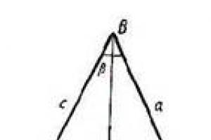
It lies in the fact that falling, And reflected Ray placed in single plane with a perpendicular to the surface, and this perpendicular divides the angle between the indicated rays into equal components.
It is often simplified as follows: corner fall and angle light reflections the same:
α = β.
The law of reflection is based on the features wave optics. It was experimentally substantiated by Euclid in the 3rd century BC. It can be considered a consequence of the use of Fermat's principle for mirror surface. Also, this law can be formulated as a consequence of the Huygens principle, according to which any point of the medium, to which the perturbation has reached, acts as a source secondary waves.
Any medium specifically reflects and absorbs light emission. The parameter describing the reflectivity of the surface of a substance is denoted as reflection coefficient(ρ orR) . Quantitatively, the reflection coefficient is equal to the ratio radiation flux, reflected by the body, to the flow that hit the body:
Light is completely reflected from a thin film of silver or liquid mercury deposited on a sheet of glass.
Allocate diffuse And mirror reflection.
Reflection coefficient is a dimensionless physical quantity that characterizes the ability of a body to reflect radiation incident on it. As letter designation Greek is used or latin .
Definitions
Quantitatively, the reflection coefficient is equal to the ratio of the radiation flux reflected by the body to the flux that fell on the body:
The sum of the reflection coefficient and the coefficients of absorption, transmission and scattering is equal to one. This statement follows from the law of conservation of energy.
In those cases where the spectrum of the incident radiation is so narrow that it can be considered monochromatic, one speaks of monochromatic reflection coefficient. If the spectrum of radiation incident on the body is wide, then the corresponding reflection coefficient is sometimes called integral.
In the general case, the value of the reflection coefficient of a body depends both on the properties of the body itself and on the angle of incidence, spectral composition, and polarization of the radiation. Due to the dependence of the reflection coefficient of the surface of the body on the wavelength of the light incident on it, the body is visually perceived as painted in one color or another.
Specular reflection coefficient
It characterizes the ability of bodies to mirror the radiation incident on them. Quantitatively determined by the ratio of the specularly reflected radiation flux to the falling stream:
Specular (directional) reflection occurs when radiation is incident on a surface whose irregularities are much smaller than the radiation wavelength.
Diffuse reflectance
Characterizes the ability of bodies to diffusely reflect the radiation incident on them. Quantitatively determined by the ratio of the diffusely reflected radiation flux to the falling stream:
If both specular and diffuse reflections occur simultaneously, then the reflection coefficient is the sum of the coefficients of the mirror image and diffuse reflections:
see also
Write a review on the article "Reflection coefficient (optics)"
Notes
An excerpt characterizing the reflectance (optics)
- Oh, Natasha! - she said.- Did you see it? Did you see? What did you see? cried Natasha, holding up the mirror.
Sonya didn’t see anything, she just wanted to blink her eyes and get up when she heard Natasha’s voice saying “by all means” ... She didn’t want to deceive either Dunyasha or Natasha, and it was hard to sit. She herself did not know how and why a cry escaped her when she covered her eyes with her hand.
- Did you see him? Natasha asked, grabbing her hand.
- Yes. Wait ... I ... saw him, ”Sonya said involuntarily, still not knowing who Natasha meant by his word: him - Nikolai or him - Andrei.
“But why shouldn’t I tell you what I saw? Because others see it! And who can convict me of what I saw or did not see? flashed through Sonya's head.
“Yes, I saw him,” she said.
- How? How? Is it worth it or is it lying?
- No, I saw ... That was nothing, suddenly I see that he is lying.
- Andrey lies? He is sick? - Natasha asked with frightened fixed eyes looking at her friend.
- No, on the contrary - on the contrary, a cheerful face, and he turned to me - and at the moment she spoke, it seemed to her that she saw what she was saying.
- Well, then, Sonya? ...
- Here I did not consider something blue and red ...
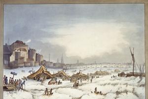
– Sonya! when will he return? When I see him! My God, how I’m afraid for him and for myself, and I’m scared for everything ... - Natasha spoke, and without answering a word to Sonya’s consolations, she lay down in bed and long after the candle was put out, with her eyes open, lay motionless on bed and looked at the frosty, moonlight through the frozen windows.
Soon after Christmas, Nikolai announced to his mother his love for Sonya and his firm decision to marry her. The countess, who had long noticed what was happening between Sonya and Nikolai, and was expecting this explanation, silently listened to his words and told her son that he could marry whomever he wanted; but that neither she nor his father would give him blessings for such a marriage. For the first time, Nikolai felt that his mother was unhappy with him, that despite all her love for him, she would not give in to him. She, coldly and without looking at her son, sent for her husband; and when he arrived, the countess wanted to briefly and coldly tell him what was the matter in the presence of Nikolai, but she could not stand it: she burst into tears of annoyance and left the room. The old count began to hesitantly admonish Nicholas and ask him to abandon his intention. Nicholas replied that he could not change his word, and his father, sighing and obviously embarrassed, very soon interrupted his speech and went to the countess. In all clashes with his son, the count did not leave the consciousness of his guilt before him for the disorder of affairs, and therefore he could not be angry with his son for refusing to marry a rich bride and for choosing a dowry Sonya - only on this occasion did he more vividly recall that, if things had not been upset, it would be impossible for Nicholas to wish for a better wife than Sonya; and that only he, with his Mitenka and his irresistible habits, is to blame for the disorder of affairs.
When passing through the boundaries between media, acoustic waves experience not only reflection and refraction, but also the transformation of waves of one type into another. Let us consider the simplest case of normal incidence of a wave on the boundary of two extended media (Fig. 3.1). There is no wave transformation in this case.
Let us consider the energy relations between the incident, reflected, and transmitted waves. They are characterized by the coefficients of reflection and refraction.
Amplitude reflection coefficient is the ratio of the amplitudes of the reflected and incident waves:
Amplitude transmission coefficient is the ratio of the amplitude of the transmitted and incident waves:
These coefficients can be determined knowing acoustic characteristics avg. When a wave is incident from medium 1 into medium 2, the reflection coefficient is determined as
 , (3.3)
where , are the acoustic impedances of media 1 and 2, respectively.
When a wave is incident from medium 1 to medium 2, the transmission coefficient is denoted and defined as
 . (3.4)
When a wave is incident from medium 2 into medium 1, the transmission coefficient is denoted and defined as
 . (3.5)
It can be seen from formula (3.3) for the reflection coefficient that the more the acoustic impedances of the media differ, the greater part of the energy of the sound wave will be reflected from the interface between the two media. This determines both the possibility and the efficiency of detecting discontinuities in the material (environment inclusions with acoustic resistance different from the resistance of the controlled material).
It is precisely because of the differences in the values of the reflection coefficients that slag inclusions are detected much worse than defects of the same size, but with air filling. The reflection from a discontinuity filled with gas approaches 100%, and for a discontinuity filled with slag, this coefficient is much lower.
When a wave is normally incident on the boundary of two extended media, the ratio between the amplitudes of the incident, reflected, and transmitted waves is
![]() . (3.6)
. (3.6)
The energy of the incident wave in the case of normal incidence on the boundary of two extended media is distributed between the reflected and transmitted waves according to the conservation law.
In addition to the reflection and amplitude transmission coefficients, the intensity reflection and transmission coefficients are also used.
Intensity reflection coefficient is the ratio of the intensities of the reflected and incident waves. For normal wave incidence
 , (3.7)
where is the reflection coefficient during the incidence from medium 1 to medium 2;
is the reflection coefficient when falling from medium 2 into medium 1.
Intensity Transmission Coefficient is the ratio of the intensities of the transmitted and incident waves. When the wave falls along the normal
 , (3.8)
where is the transmission coefficient during the fall from medium 1 to medium 2;
is the transmission coefficient when falling from medium 2 to medium 1.
The direction of wave incidence does not affect the values of the coefficients of reflection and intensity transmission. The law of conservation of energy through the coefficients of reflection and transmission is written as follows
When a wave is obliquely incident on the interface between media, it is possible to transform a wave of one type into another. The reflection and transmission processes in this case are characterized by several reflection and transmission coefficients, depending on the type of incident, reflected, and transmitted waves. The reflection coefficient in this form has the designation ( is an index indicating the type of the incident wave, is an index indicating the type of the reflected wave). Cases are possible. The transmission coefficient is denoted by ( is an index indicating the type of the incident wave, is an index indicating the type of the transmitted wave). There are cases , and .