Counting angles on a trigonometric circle.
Attention!
There are additional
materials in Special Section 555.
For those who are very "not very..."
And for those who “very much…”)
It is almost the same as in the previous lesson. There are axes, a circle, an angle, everything is in order. Added quarter numbers (in the corners of the large square) - from the first to the fourth. What if someone doesn’t know? As you can see, the quarters (they are also called the beautiful word “quadrants”) are numbered counterclockwise. Added angle values on axes. Everything is clear, no problems.
And a green arrow is added. With a plus. What does it mean? Let me remind you that the fixed side of the angle Always nailed to the positive semi-axis OX. So, if we rotate the movable side of the angle along the arrow with a plus, i.e. in ascending order of quarter numbers, the angle will be considered positive. As an example, the picture shows a positive angle of +60°.
If we put aside the corners in the opposite direction, clockwise, the angle will be considered negative. Hover your cursor over the picture (or touch the picture on your tablet), you will see a blue arrow with a minus sign. This is the direction of negative angle reading. For example, a negative angle (- 60°) is shown. And you will also see how the numbers on the axes have changed... I also converted them to negative angles. The numbering of the quadrants does not change.
This is where the first misunderstandings usually begin. How so!? What if a negative angle on a circle coincides with a positive one!? And in general, it turns out that the same position of the moving side (or point on the number circle) can be called both a negative angle and a positive one!?
Yes. Exactly. Let's say a positive angle of 90 degrees takes on a circle exactly the same position as a negative angle of minus 270 degrees. A positive angle, for example, +110° degrees takes exactly the same position as negative angle -250°.
No problem. Anything is correct.) The choice of positive or negative angle calculation depends on the conditions of the task. If the condition says nothing in clear text about the sign of the angle, (like "determine the smallest positive angle", etc.), then we work with values that are convenient for us.
The exception (how could we live without them?!) are trigonometric inequalities, but there we will master this trick.
And now a question for you. How did I know that the position of the 110° angle is the same as the position of the -250° angle?
Let me hint that this is connected with a complete revolution. In 360°... Not clear? Then we draw a circle. We draw it ourselves, on paper. Marking the corner approximately 110°. AND we think, how much time remains until a full revolution. Just 250° will remain...
Got it? And now - attention! If angles 110° and -250° occupy a circle same
situation, then what? Yes, the angles are 110° and -250° exactly the same
sine, cosine, tangent and cotangent!
Those. sin110° = sin(-250°), ctg110° = ctg(-250°) and so on. Now this is really important! And in itself, there are a lot of tasks where you need to simplify expressions, and as a basis for the subsequent mastery of reduction formulas and other intricacies of trigonometry.
Of course, I took 110° and -250° at random, purely as an example. All these equalities work for any angles occupying the same position on the circle. 60° and -300°, -75° and 285°, and so on. Let me note right away that the angles in these pairs are different. But they have trigonometric functions - the same.
I think you understand what negative angles are. It's quite simple. Counterclockwise - positive counting. Along the way - negative. Consider the angle positive or negative depends on us. From our desire. Well, and also from the task, of course... I hope you understand how to move in trigonometric functions from negative angles to positive ones and back. Draw a circle, an approximate angle, and see how much is missing to complete a full revolution, i.e. up to 360°.
Angles greater than 360°.
Let's deal with angles that are greater than 360°. Are there such things? There are, of course. How to draw them on a circle? No problem! Let's say we need to understand which quarter an angle of 1000° will fall into? Easily! We make one full turn counterclockwise (the angle we were given is positive!). We rewinded 360°. Well, let's move on! One more turn - it’s already 720°. How much is left? 280°. It’s not enough for a full turn... But the angle is more than 270° - and this is the border between the third and fourth quarter. Therefore, our angle of 1000° falls into the fourth quarter. All.
As you can see, it's quite simple. Let me remind you once again that the angle of 1000° and the angle of 280°, which we obtained by discarding the “extra” full revolutions, are, strictly speaking, different corners. But the trigonometric functions of these angles exactly the same! Those. sin1000° = sin280°, cos1000° = cos280°, etc. If I were a sine, I wouldn't notice the difference between these two angles...
Why is all this needed? Why do we need to convert angles from one to another? Yes, all for the same thing.) In order to simplify expressions. Simplifying expressions is, in fact, the main task of school mathematics. Well, and, along the way, the head is trained.)
Well, let's practice?)
We answer questions. Simple ones first.
1. Which quarter does the -325° angle fall into?
2. Which quarter does the 3000° angle fall into?
3. Which quarter does the angle -3000° fall into?
There is a problem? Or uncertainty? Go to Section 555, Trigonometric Circle Practice. There, in the first lesson of this very “Practical work...” everything is detailed... In such questions of uncertainty to be shouldn't!
4. What sign does sin555° have?
5. What sign does tg555° have?
Have you determined? Great! Do you have any doubts? You need to go to Section 555... By the way, there you will learn to draw tangent and cotangent on a trigonometric circle. A very useful thing.
And now the questions are more sophisticated.
6. Reduce the expression sin777° to the sine of the smallest positive angle.
7. Reduce the expression cos777° to the cosine of the largest negative angle.
8. Reduce the expression cos(-777°) to the cosine of the smallest positive angle.
9. Reduce the expression sin777° to the sine of the largest negative angle.
What, questions 6-9 puzzled you? Get used to it, on the Unified State Exam you don’t find such formulations... So be it, I’ll translate it. Only for you!
The words "bring an expression to..." mean to transform the expression so that its meaning hasn't changed and the appearance changed in accordance with the task. So, in tasks 6 and 9 we must get a sine, inside of which there is smallest positive angle. Everything else doesn't matter.
I will give out the answers in order (in violation of our rules). But what to do, there are only two signs, and there are only four quarters... You won’t be spoiled for choice.
6. sin57°.
7. cos(-57°).
8. cos57°.
9. -sin(-57°)
I assume that the answers to questions 6-9 confused some people. Especially -sin(-57°), really?) Indeed, in the elementary rules for calculating angles there is room for errors... That is why I had to do a lesson: “How to determine the signs of functions and give angles on a trigonometric circle?” In Section 555. Tasks 4 - 9 are covered there. Well sorted, with all the pitfalls. And they are here.)
In the next lesson we will deal with the mysterious radians and the number "Pi". Let's learn how to easily and correctly convert degrees to radians and vice versa. And we will be surprised to discover that this basic information on the site enough already to solve some custom trigonometry problems!
If you like this site...
By the way, I have a couple more interesting sites for you.)
You can practice solving examples and find out your level. Testing with instant verification. Let's learn - with interest!)
You can get acquainted with functions and derivatives.
It characterizes the maximum angle at which a car wheel will turn when the steering wheel is fully turned. And the smaller this angle, the greater the accuracy and smoothness of control. After all, to turn even a small angle, only a small movement of the steering wheel is required.But do not forget that the smaller the maximum turning angle, the smaller the turning radius of the car. Those. It will be very difficult to turn around in a confined space. So manufacturers have to look for some kind of “golden mean”, maneuvering between a large turning radius and control accuracy.
Changing wheel alignment angles and adjusting them
The Piri Reis map has been compared with a modern map projection. Thus, he came to the conclusion that a mysterious map was taking over the world, as seen from a satellite hovering high above Cairo. In other words, above the Great Pyramid. It is surprising that Egyptologists continually defend these spaces, although one recently discovered corridor has been reviewed and has yet to yield any breakthroughs.
It is also worth noting that unusual psychotronic effects have been found in the pyramid, which, among other things, can affect human health. We are talking about spatial psychotronics, creating both energetic and geomagnetic “anomalous zones”, which are further investigated.
Roll shoulder is the shortest distance between the middle of the tire and the steering axis of the wheel. If the axis of rotation of the wheel and the middle of the wheel coincide, then the value is considered zero. With a negative value, the rotation axis will move outward of the wheel, and with a positive value, it will move inward.When the wheel turns, the tire is deformed under the influence of lateral forces. And in order to maintain the maximum contact patch with the road, the car’s wheel also tilts in the direction of the turn. But everywhere you need to know when to stop, because with a very large caster, the car’s wheel will tilt strongly and then lose traction.
 Responsible for weight stabilization of the steered wheels. The point is that the moment the wheel deviates from neutral, the front end begins to rise. And since it weighs a lot, when the steering wheel is released under the influence of gravity, the system tends to take its initial position, corresponding to movement in a straight line. True, for this stabilization to work, it is necessary to maintain the (albeit small, but undesirable) positive roll-in shoulder.
 Initially, the transverse angle of the steering axis was used by engineers to eliminate the shortcomings of the car's suspension. It got rid of such “illnesses” of the car as positive camber and positive rolling shoulder.
During archaeological excavations, strange funeral offerings in the form of birds with outstretched wings were also found. Later aerodynamic studies of these subjects revealed that they were most likely ancient glider models. One of them was discovered with the inscription "gift of Amon." The god Amun in Egypt was worshiped as the god of the wind so associated with flight is obvious.
But how did the members of this ancient civilization come to this knowledge without a preliminary stage of development? The answer in this case is only. This knowledge came from the governments of those times, which the Egyptians called their gods. It is possible for members of a technologically advanced civilization that dates back more than 000 years to have disappeared without a trace.
Many cars use MacPherson type suspension. It makes it possible to obtain a negative or zero rolling leverage. After all, the steering axis of the wheel consists of the support of one single lever, which can easily be placed inside the wheel. But this suspension is not perfect either, because due to its design, it is almost impossible to make the angle of inclination of the turning axis small. When turning, it tilts the outer wheel at an unfavorable angle (like positive camber), while the inner wheel simultaneously leans in the opposite direction.
But such facilities are still in short supply. They fall apart, they can be destroyed, but it can also be well hidden in temples, pyramids and other iconic buildings that can lie motionless, properly secured against "treasure hunters".
The Great Pyramid's size and design precision have never been equaled. The pyramid weighs approximately six million tons. In its position as the Eiffel Tower, the Great Pyramid was the tallest building in the world. More than two million stones were used for its construction. Not a single stone weighs less than a ton.
As a result, the contact patch of the outer wheel is greatly reduced. And since the outer wheel bears the main load when turning, the entire axle loses a lot of traction. This, of course, can be partially compensated for by caster and camber. Then the grip of the outer wheel will be good, but that of the inner wheel will practically disappear.
Car wheel alignment
 There are two types of car alignment: positive and negative. Determining the type of alignment is very simple: you need to draw two straight lines along the wheels of the car. If these lines intersect at the front of the car, then the toe is positive, and if at the rear, it is negative. If there is positive toe-in of the front wheels, the car will make it easier to turn and will also gain additional steering ability.
 On the rear axle, with positive toe-in, the car will be more stable when moving in a straight line, but if there is negative toe-in, the car will behave inappropriately and yaw from side to side.
And some of over seventy tons. Inside, the cells are connected by corridors. Today, it is a rough stone pyramid, but once it was processed to the mirror shine of the masonry. The peak of the Great Pyramid is believed to have been decorated with pure gold. The sun's rays blinded hundreds of kilometers. For centuries, experts have speculated about the purpose of the pyramids. Traditional theory states that the pyramids were a symbolic gateway to the afterlife. Others believe that the pyramid was an astronomical observatory. Some say that the help is in the geographical dimension.
But it should be remembered that excessive deviation of the car’s toe from zero will increase rolling resistance during straight-line movement; in corners this will be less noticeable.
Wheel camber
 Wheel camber, like toe-in, can be either negative or positive.
 If you look from the front of the car, and the wheels tilt inward, then this is negative camber, and if they lean outward of the car, then this is positive camber. Wheel camber is necessary to maintain traction between the wheel and the road surface.
One fanciful theory claims that the Great Pyramid was on granaries. However, experts today generally agree that the pyramids were much more than just a giant tomb. Scientists argue that the massive pyramid technology could not have been available to people at this point in human history when these buildings were built. For example, the height of the pyramid corresponds to the distance from the Earth to the Sun. The pyramid was precisely oriented to the four worlds with a precision that has never been achieved.
And surprisingly, the Great Pyramid lies in the exact center of the earth. Whoever built the Great Pyramid could accurately determine latitude and longitude. This is surprising because the technology for determining longitude was discovered in modern times in the sixteenth century. The pyramids were built at the exact center of the Earth. Also, the height of the pyramid can be seen from a great height, can be seen from the Moon. Moreover, the pyramid shape is one of the best for reflecting radars. These reasons lead some researchers to believe that the Egyptian pyramids were built outside of their other purposes and for navigation by potential foreign explorers.
Changing the camber angle affects the behavior of the car on a straight line, because the wheels are not perpendicular to the road, which means they do not have maximum grip. But this only affects rear-wheel drive cars when starting from a stop with slipping.
› All about wheel alignment angles part 1.For those who want to understand what Wheel Alignment Angles (Camber/Toe) mean and thoroughly understand the issue, this article has answers to all questions.
The Pyramid of Cheops is located just over eight kilometers west of Cairo. It is built on an artificially created flat with an area of 1.6 square kilometers. Its base extends up to 900 square meters and is almost millimeter wide when horizontal. Two and three quarters of a million stone blocks were used for the construction, with the heaviest weighing up to 70 tons. They fit in such a way that this fact is a mystery. However, the technical side of creating the pyramid remains a mystery, as it would be a major challenge for today's advanced technology.
An excursion into history shows that sophisticated wheel installations were used on various vehicles long before the advent of the automobile. Here are a few more or less well-known examples.
It is no secret that the wheels of some carriages and other horse-drawn carriages, intended for “dynamic” driving, were installed with a large, clearly visible positive camber. This was done so that the dirt flying from the wheels did not fall into the carriage and important riders, but was scattered to the sides. For utilitarian carts for leisurely movement, everything was exactly the opposite. Thus, pre-revolutionary manuals on how to build a good cart recommended installing wheels with negative camber. In this case, if the dowel stopping the wheel was lost, it did not immediately jump off the axle. The driver had time to notice the damage to the chassis, which was fraught with especially big troubles if there were several dozen pounds of flour in the cart and there was no jack. In the design of gun carriages (again, vice versa), positive camber was sometimes used. It is clear that it was not intended to protect the gun from dirt. This made it convenient for the servant to roll the gun by the wheels with his hands from the side, without fear of crushing his legs. But the cart’s huge wheels, which made it easy to get over the ditches, were tilted in the other direction - towards the cart. The resulting increase in track helped to increase the stability of the Central Asian “mobile,” which was distinguished by a high center of gravity. What do these historical facts have to do with the installation of wheels on modern cars? Yes, in general, none. However, they provide a useful insight. It can be seen that the installation of wheels (in particular, their camber) is not subject to any single pattern.
Therefore, there is no hypothesis that magical powers were used in the construction of the pyramid - magical formulas written on papyrus made it possible to move heavy pieces of stone and place them on top of each other with amazing precision. Edgar Cayce said that these pyramids were built ten thousand years ago, while others believe that the pyramids were built by Atlanteans who, before the cataclysm that destroyed their continent, mainly sought refuge in Egypt. He creates scientific centers, they also created a pyramidal shelter where great secrets could be hidden.
When choosing this parameter, the “manufacturer” in each specific case was guided by different considerations, which he considered priority. So, what do car suspension designers strive for when choosing a suspension system? Of course, towards the ideal. The ideal for a car that moves in a straight line is considered to be the position of the wheels when the planes of their rotation (rolling planes) are perpendicular to the road surface, parallel to each other, the axis of symmetry of the body and coincide with the trajectory of movement. In this case, power loss due to friction and wear of the tire tread is minimal, and the traction of the wheels with the road, on the contrary, is maximum. Naturally, the question arises: what makes you deliberately deviate from the ideal? Looking ahead, several considerations can be given. First, we judge wheel alignment based on a static picture when the car is stationary. Who said that when driving, accelerating, braking and maneuvering a car, it does not change? Secondly, reducing losses and extending tire life is not always a priority. Before talking about what factors suspension developers take into account, let’s agree that from the large number of parameters that describe the geometry of a car’s suspension, we will limit ourselves to only those that are included in the group of primary or basic ones. They are called so because they determine the settings and properties of the suspension, are always monitored during its diagnosis and are adjusted, if such a possibility is provided. These are the well-known toe, camber and steering angles of the steering wheels. When considering these most important parameters, we will have to remember other characteristics of the suspension.
The pyramid consists of 203 layers of stone blocks weighing from 2.5 to 15 tons. Some blocks at the bottom of the pyramid at the base weigh up to 50 tons. Originally, the entire pyramid was covered with a fine white and polished limestone shell, but the stone was used for construction, especially after frequent earthquakes in the area.
The weight of the pyramid is proportional to the weight of the Earth 1:10. The pyramid is a maximum of 280 Egyptian cubits, and the base area is 440 Egyptian cubits. If the basic pattern is divided by double the height of the pyramid, we get the Ludolf number - 3. The deviation from the Ludolf figure is only 0.05%. The base of the base is equal to the circumference of a circle with a radius equal to the height of the pyramid.

Toe-in (TOE) characterizes the orientation of the wheels relative to the longitudinal axis of the vehicle. The position of each wheel can be determined separately from the others, and then they speak of individual toe. It represents the angle between the plane of rotation of the wheel and the axis of the car when viewed from above. Total toe-in (or simply toe-in) of wheels on one axle. as the name suggests, it is the sum of individual angles. If the planes of rotation of the wheels intersect in front of the car, the toe-in is positive (toe-in), if at the rear it is negative (toe-out). In the latter case, we can talk about wheel misalignment.
In adjustment data, convergence is sometimes given not only as an angular, but also as a linear value. This is related to that. that the toe-in of the wheels is also judged by the difference in the distances between the flanges of the rims, measured at the level of their centers behind and in front of the axle.
Whatever the truth, perhaps archaeologists will, of course, recognize the skill of ancient builders, for example. Flinders Petrie concluded that the errors in the measurements were so small that he pinched his finger. The walls connecting the corridors, falling 107 m into the center of the pyramid, showed a deviation of only 0.5 cm from ideal accuracy. Can we explain the mystery of the Pharaoh's pyramid to the pedantry of the architects and builders, or to the unknown magic of Egypt, or to the simple necessity of keeping the dimensions as close as possible to achieve the maximum benefit of the pyramid?
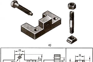
Various sources, including serious technical literature, often give the version that wheel alignment is necessary to compensate for the side effects of camber. They say that due to the deformation of the tire in the contact patch, the “collapsed” wheel can be imagined as the base of a cone. If the wheels are installed with a positive camber angle (why is not important yet), they tend to “roll” in different directions. To counteract this, the planes of rotation of the wheels are brought together (Fig. 20)
Is it just a coincidence that this number expresses the distance from the Sun, which is reported in millions of miles? An Egyptian cubit is exactly one ten-millimeter radius of the earth. The Great Pyramid expresses the 2p relationship between the circumference and radius of the Earth. Circle The square area of a circle is 023 feet.
He also discusses the similarities between the figures in Nazca, the Great Pyramid, and Egyptian hieroglyphic texts. Bowles notes that the Great Pyramid and Nazca Plateau will be on the equator when the North Pole is located in southeast Alaska. Using coordinates and spherical trigonometry, the book demonstrates the remarkable connections between three ancient sites.

The version, it must be said, is not without grace, but does not stand up to criticism. If only because it assumes an unambiguous relationship between camber and toe. Following the proposed logic, wheels with a negative camber angle must necessarily be installed with divergence, and if the camber angle is zero, then there should be no toe-in. In reality this is not the case at all.
Of course, this connection also exists between the Great Pyramid, the Nazca Plate and the "ancient lineage" axis, regardless of where the North Pole is located. This relationship can be used to determine the distances between three points and a plane. In the royal chamber the diagonal is 309 from the eastern wall, the distance from the chamber is 412, the middle diagonal is 515.
The distances between Ollantaytambo, the Great Pyramid and the Axis Point on the Ancient Line express the same geometric relationship. 3-4 The distance of the Great Pyramid from Ollantaytambo is exactly 30% of the periphery of the Earth. The distance from the Great Pyramid to Machu Picchu and the Axis Point in Alaska is 25% of the earth's perimeter. By stretching this isosceles triangle in height, we get two right triangles with sides from 15% to 20% - 25%.
Reality, as usual, is subject to more complex and ambiguous laws. When an inclined wheel rolls, a lateral force is actually present in the contact patch, which is often called camber thrust. It occurs as a result of elastic deformation of the tire in the transverse direction and acts in the direction of inclination. The greater the angle of inclination of the wheel, the greater the camber thrust. This is what drivers of two-wheeled vehicles - motorcycles and bicycles - use when cornering. They only need to tilt their horse to force it to “prescribe” a curved trajectory, which can only be corrected by steering. Camber thrust also plays an important role when maneuvering cars, which will be discussed below. So it’s unlikely that it should be intentionally compensated for by toe-in. And the message itself is that due to a positive camber angle, the wheels tend to turn outward, i.e. towards divergence, incorrect. On the contrary, the design of the steering wheel suspension in most cases is such that with positive camber its thrust tends to increase toe-in. So “compensation for the side effects of camber” has nothing to do with it. There are several known factors that determine the need for wheel alignment. The first is that the previously set toe-in compensates for the influence of longitudinal forces acting on the wheel when the car is moving. The nature and depth (and therefore the result) of the influence depend on many circumstances: the drive wheel is either free-rolling, controlled, or not, and finally, on the kinematics and elasticity of the suspension. Thus, a rolling resistance force acts on a freely rolling car wheel in the longitudinal direction. It creates a bending moment that tends to rotate the wheel relative to the suspension mounting points in the direction of divergence. If the car's suspension is rigid (for example, not a split or torsion beam), then the effect will not be very significant. Nevertheless, it will definitely happen, since “absolute rigidity” is a purely theoretical term and phenomenon. In addition, the movement of the wheel is determined not only by the elastic deformation of the suspension elements, but also by the compensation of structural gaps in their connections, wheel bearings, etc.
In the case of a suspension with high compliance (which is typical, for example, for lever structures with elastic bushings), the result will increase many times over. If the wheel is not only free-rolling, but also steerable, the situation becomes more complicated. Due to the appearance of an additional degree of freedom at the wheel, the same resistance force has a double effect. The moment that bends the front suspension is complemented by a moment that tends to turn the wheel around the turning axis. The turning moment, the magnitude of which depends on the location of the steering axis, affects the parts of the steering mechanism and, due to their compliance, also makes a significant contribution to the change in wheel toe in motion. Depending on the running arm, the contribution of the turning moment can be with a “plus” or “minus” sign. That is, it can either increase wheel divergence or counteract it. If you do not take all this into account and initially install wheels with zero toe, they will take a divergent position when moving. From this will follow the consequences characteristic of cases of violation of toe adjustment: increased fuel consumption, saw-tooth tread wear and problems with handling, which will be discussed below.
The force of resistance to movement depends on the speed of the car. Therefore, the ideal solution would be variable toe, providing the same ideal wheel position at any speed. Since this is difficult to do, the wheel is pre-adjusted so as to achieve minimal tire wear at cruising speed. The wheel located on the drive axle is exposed to traction force most of the time. It exceeds the forces of resistance to movement, so the resultant forces will be directed in the direction of movement. Applying the same logic, we find that in this case the static wheels need to be installed with a discrepancy. A similar conclusion can be drawn regarding the steered drive wheels.
The best criterion of truth is practice. If, with this in mind, you look at the adjustment data for modern cars, you may be disappointed not to find much difference in the toe-in of the steering wheels of rear- and front-wheel drive models. In most cases, for both of them this parameter will be positive. Except that among front-wheel drive cars, cases of “neutral” toe adjustment are more common. The reason is not that the above logic is not correct. It’s just that when choosing the amount of toe-in, along with compensation of longitudinal forces, other considerations are taken into account that make adjustments to the final result. One of the most important is ensuring optimal vehicle handling. With increasing speeds and the dynamism of vehicles, this factor is becoming increasingly important.
Handling is a multifaceted concept, so it is worth clarifying that wheel toe most significantly affects the stabilization of the straight trajectory of the car and its behavior when entering a turn. This influence can be clearly illustrated using the example of steered wheels.

Suppose, while moving in a straight line, one of them is subject to a random disturbance from the unevenness of the road. The increased resistance force turns the wheel in the direction of decreasing toe. Through the steering mechanism, the impact is transmitted to the second wheel, the toe of which, on the contrary, increases. If the wheels initially have positive toe-in, the drag force on the first one decreases, and on the second one it increases, which counteracts the disturbance. When the convergence is zero, there is no counteracting effect, and when it is negative, a destabilizing moment appears, contributing to the development of disturbance. A car with such a toe adjustment will wander along the road and will have to be constantly caught by steering, which is unacceptable for an ordinary road car.
This “coin” also has a reverse, positive side - negative toe-in allows you to achieve the fastest response from the steering. The slightest action by the driver immediately provokes a sharp change in trajectory - the car willingly maneuvers, easily “agrees” to turn. This type of toe adjustment is often used in motorsports.

Those who watch TV shows about the WRC championship have probably noticed how actively Loeb or Grönholm have to work at the wheel, even on relatively straight sections of the track. The toe-in of the rear axle wheels has a similar effect on the behavior of the car - reducing the toe-in down to a slight divergence increases the “mobility” of the axle. This effect is often used to compensate for the understeer of cars, for example, front-wheel drive models with an overloaded front axle.
Thus, the static toe-in parameters, which are given in the adjustment data, represent a kind of superposition, and sometimes a compromise, between the desire to save on fuel and tires and achieve optimal handling characteristics for the car. Moreover, it is noticeable that in recent years the latter has prevailed.
Camber is a parameter that is responsible for the orientation of the wheel relative to the road surface. We remember that ideally they should be perpendicular to each other, i.e. there shouldn't be any collapse. However, most road cars have one. What's the trick?
Reference.
Camber reflects the orientation of the wheel relative to the vertical and is defined as the angle between the vertical and the plane of rotation of the wheel. If the wheel is actually “broken”, i.e. its top is inclined outward, the camber is considered positive. If the wheel is tilted towards the body, the camber is negative.

Until recently, there was a tendency for wheels to fall apart, i.e. give camber angles positive values. Many people probably remember textbooks on automobile theory, in which the installation of cambered wheels was explained by the desire to redistribute the load between the outer and inner wheel bearings. They say that with a positive camber angle, most of it falls on the internal bearing, which is easier to make more massive and durable. As a result, the durability of the bearing assembly benefits. The thesis is not very convincing, if only because if it is true, it is only for an ideal situation - straight-line movement of a car on an absolutely flat road. It is known that when maneuvering and driving over irregularities, even the most minor ones, the bearing assembly experiences dynamic loads that are an order of magnitude greater than static forces. And they are not distributed exactly as the positive camber “dictates”.
Sometimes they try to interpret positive camber as an additional measure aimed at reducing the running-in shoulder. When we get to the point of getting to know this important parameter of the steering wheel suspension, it will become clear that this method of influence is far from the most successful. It is associated with a simultaneous change in the track width and the included angle of inclination of the wheel steering axis, which is fraught with undesirable consequences. There are more direct and less painful options for changing the break-in shoulder. In addition, its minimization is not always the goal of suspension developers.
A more convincing version is that positive camber compensates for the wheel displacement that occurs when the axle load increases (as a result of an increase in vehicle load or dynamic redistribution of its mass during acceleration and braking). The elasto-kinematic properties of most types of modern suspensions are such that as the weight on the wheel increases, the camber angle decreases. In order to ensure maximum traction of the wheels with the road, it is logical to first “break them apart” a little. Moreover, in moderate doses, camber does not significantly affect rolling resistance and tire wear.

It is reliably known that the choice of camber value is also influenced by the generally accepted profiling of the road surface. In civilized countries, where there are roads and not directions, their cross-section has a convex profile. In order for the wheel to remain perpendicular to the supporting surface in this case, it needs to be given a small positive camber angle.
Looking through the specifications on the UUK, you can notice that in recent years the opposite “collapse trend” has prevailed. The wheels of most production cars are statically installed with negative camber. The fact is that, as already mentioned, the task of ensuring their best stability and controllability comes to the fore. Camber is a parameter that has a decisive influence on the so-called lateral reaction of the wheels. It is this that counteracts the centrifugal forces acting on the car when turning and helps keep it on a curved path. From general considerations it follows that the adhesion of the wheel to the road (lateral reaction) will be maximum with the largest contact patch area, i.e. with the wheel in a vertical position. In fact, for a standard wheel design it reaches a peak at small negative lean angles, which is due to the contribution of the mentioned camber thrust. This means that in order to make the car’s wheels extremely grippy when turning, you don’t need to break them apart, but, on the contrary, “dump them.” This effect has been known for a long time and has been used in motorsports for just as long. If you take a closer look at the “formula” car, you can clearly see that its front wheels are installed with a large negative camber.


What is good for racing cars is not entirely suitable for production cars. Excessive negative camber causes increased wear on the inner tread area. As the wheel inclination increases, the contact patch area decreases. Wheel traction during straight-line motion decreases, which in turn reduces the efficiency of acceleration and braking. Excessive negative camber affects the car’s ability to maintain a straight trajectory in the same way as insufficient toe-in; the car becomes overly nervous. The same camber thrust is to blame for this. In an ideal situation, the lateral forces caused by the camber act on both wheels of the axle and balance each other. But as soon as one of the wheels loses traction, the camber thrust of the other turns out to be uncompensated and causes the car to deviate from a straight trajectory. By the way, if you remember that the amount of traction depends on the inclination of the wheel, it is not difficult to explain the lateral pull of the car at unequal camber angles of the right and left wheels. In a word, when choosing the camber value, you also have to look for the “golden mean”.
To ensure good stability of the car, it is not enough to make the camber angles negative in static conditions. Suspension designers must ensure that the wheels maintain optimal (or close to it) orientation in all driving modes. This is not easy to do, since during maneuvers any changes in the position of the body, accompanied by displacement of the suspension elements (dive, side rolls, etc.), lead to a significant change in the camber of the wheels. Oddly enough, this problem is solved more easily on sports cars with their “brutal” suspensions, characterized by high angular rigidity and short strokes. Here, the static values of camber (and toe) differ least from how they look in dynamics.

The greater the range of suspension travel, the greater the change in camber while driving. Therefore, the hardest thing is for developers of conventional road cars with maximally elastic (for the best comfort) suspensions. They have to rack their brains over how to “combine the incompatible” - comfort and stability. Usually a compromise can be found by “conjuring” the suspension kinematics.
There are solutions to minimize changes in camber angles and give these changes the desired “trend”. For example, it is desirable that when turning, the most loaded outer wheel would remain in that very optimal position - with a slight negative camber. To do this, when the body rolls, the wheel must “fall” onto it even more, which is achieved by optimizing the geometry of the suspension guide elements. In addition, they try to reduce the body roll itself by using anti-roll bars.
To be fair, it should be said that suspension elasticity is not always the enemy of stability and handling. In “good hands,” elasticity, on the contrary, contributes to them. For example, with skillful use of the “self-steering” effect of the rear axle wheels. Returning to the topic of conversation, we can summarize that the camber angles, which are indicated in the specifications for passenger cars, will differ significantly from what they will be in a turn.

Concluding the “disassembly” with alignment and camber, we can mention one more interesting aspect that has practical significance. The regulatory data on the control unit does not provide absolute values of camber and toe angles, but ranges of permissible values. The tolerances for toe-in are tighter and usually do not exceed ±10", while for camber they are several times looser (on average ±30"). This means that the master performing the adjustment of the control unit can adjust the suspension without going beyond the factory specifications. It would seem that several tens of arc minutes are nonsense. I entered the parameters into the “green corridor” - and order was achieved. But let's see what the result might be. For example, the specifications for the BMW 5 Series in the E39 body indicate: toe 0°5"±10", camber -0°13"±30". This means that, while remaining in the “green corridor”, the toe can take a value from –0°5" to 5", and the camber from –43" to 7". That is, both toe and camber can be negative, neutral or positive. Having an idea of the influence of toe-in and camber on the behavior of the car, you can deliberately “tamper” these parameters so as to obtain the desired result. The effect will not be dramatic, but it will definitely be there.
The camber and toe we considered are parameters that are determined for all four wheels of the car. Next, we will talk about angular characteristics that relate only to the steered wheels and determine the spatial orientation of their rotation axis.
It is known that the position of the steering axis of a car's steering wheel is determined by two angles: longitudinal and transverse. Why not make the rotation axis strictly vertical? Unlike cases with camber and alignment, the answer to this question is more unambiguous. There is almost unanimous agreement here, at least with regard to the longitudinal angle of inclination - caster.

It is rightly noted that the main function of caster is high-speed (or dynamic) stabilization of the car’s steered wheels. Stabilization in this case is the ability of the steered wheels to resist deviation from the neutral (corresponding to linear motion) position and automatically return to it after the cessation of the external forces that caused the deviation. A moving car wheel is constantly subject to disturbing forces that tend to push it out of its neutral position. They may be a result of driving over uneven roads, unbalanced wheels, etc. Since the magnitude and direction of disturbances are constantly changing, their impact is randomly oscillatory. Without a stabilization mechanism, the driver would have to counter the vibrations, which would make driving a pain and would certainly increase tire wear. With proper stabilization, the car moves steadily in a straight line with minimal driver intervention and even with the steering wheel released.

Deflection of the steered wheels can be caused by intentional actions of the driver associated with changing the direction of movement. In this case, the stabilizing effect assists the driver when exiting a corner by automatically returning the wheels to neutral. But at the entrance to the turn and at its apex, the “driver,” on the contrary, has to overcome the “resistance” of the wheels, applying a certain force to the steering wheel. The reaction force generated at the steering wheel creates what is called steering feel or steering feel, which is something that has received a lot of attention from both car designers and automotive journalists.
Let's call the rotation of the moving radius vector in the counterclockwise direction positive, and in the opposite direction (clockwise direction) negative. The angle described by the negative rotation of the moving radius vector will be called a negative angle.
Rule. The angle is measured with a positive number if it is positive and a negative number if it is negative.
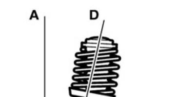
Example 1. In Fig. 80 shows two angles with a common starting side OA and a common ending side OD: one is equal to +270°, the other -90°.
The sum of two angles. On the coordinate plane Oxy, consider a circle of unit radius with the center at the origin (Fig. 81).
Let an arbitrary angle a (positive in the drawing) be obtained as a result of the rotation of a certain moving radius vector from its initial position OA, coinciding with the positive direction of the Ox axis, to its final position.


Let us now take the position of the radius vector OE as the initial one and set aside an arbitrary angle from it (positive in the drawing), which we obtain as a result of rotating a certain moving radius vector from its initial position OE to its final position OS. As a result of these actions, we will obtain an angle, which we will call the sum of angles a and . (Initial position of the moving radius vector OA, final position of the radius vector OS.)
Difference between two angles.
By the difference of two angles a and , which we denote we will understand the third angle y, which in sum with the angle gives angle a, i.e. if the difference of two angles can be interpreted as the sum of angles a and . In fact, in general, for any angles their sum is measured by the algebraic sum of the real numbers that measure these angles.
Example 2. then .
Example 3. Angle , and angle . The sum of them.
In formula (95.1) it was assumed that - any non-negative integer. If we assume that is any integer (positive, negative or zero), then using the formula
![]()
where you can write any angle, both positive and negative.

Example 4. An angle equal to -1370° can be written as follows:
Note that all angles written using formula (96.1), with different values of , but the same a, have common initial (OA) and final (OE) sides (Fig. 79). Therefore, the construction of any angle is reduced to the construction of the corresponding non-negative angle less than 360°. In Fig. 79 angles do not differ from each other; they differ only in the process of rotation of the radius vector, which led to their formation.
An important concept in trigonometry is angle of rotation. Below we will consistently give an idea of the turn and introduce all the related concepts. Let's start with a general idea of a turn, say a full rotation. Next, let's move on to the concept of rotation angle and consider its main characteristics, such as the direction and magnitude of rotation. Finally, we give the definition of rotation of a figure around a point. We will provide the entire theory in the text with explanatory examples and graphic illustrations.
Page navigation.
What is called the rotation of a point around a point?
Let us immediately note that, along with the phrase “rotation around a point,” we will also use the phrases “rotation about a point” and “rotation about a point,” which mean the same thing.
Let's introduce concept of turning a point around a point.
First, let's define the center of rotation.
Definition.
The point about which the rotation is made is called center of rotation.
Now let's say what happens as a result of rotating the point.
As a result of rotating a certain point A relative to the center of rotation O, a point A 1 is obtained (which, in the case of a certain number, may coincide with A), and point A 1 lies on a circle with a center at point O of radius OA. In other words, when rotated relative to point O, point A goes to point A 1 lying on a circle with a center at point O of radius OA.
It is believed that point O, when turning around itself, turns into itself. That is, as a result of rotation around the center of rotation O, point O turns into itself.
It is also worth noting that the rotation of point A around point O should be considered as a displacement as a result of the movement of point A in a circle with a center at point O of radius OA.
For clarity, we will give an illustration of the rotation of point A around point O; in the figures below, we will show the movement of point A to point A 1 using an arrow.
Full turn
It is possible to rotate point A relative to the center of rotation O, such that point A, having passed all the points of the circle, will be in the same place. In this case, they say that point A has moved around point O.
Let's give a graphic illustration of a complete revolution.

If you do not stop at one revolution, but continue to move the point around the circle, then you can perform two, three, and so on full revolutions. The drawing below shows how two full turns can be made on the right and three turns on the left.

Rotation angle concept
From the concept of rotating a point introduced in the first paragraph, it is clear that there are an infinite number of options for rotating point A around point O. Indeed, any point on a circle with a center at point O of radius OA can be considered as point A 1 obtained as a result of rotating point A. Therefore, to distinguish one turn from another, we introduce concept of rotation angle.
One of the characteristics of the rotation angle is direction of rotation. The direction of rotation determines whether the point is rotated clockwise or counterclockwise.
Another characteristic of the rotation angle is its magnitude. Rotation angles are measured in the same units as: degrees and radians are the most common. It is worth noting here that the angle of rotation can be expressed in degrees by any real number from minus infinity to plus infinity, in contrast to the angle in geometry, the value of which in degrees is positive and does not exceed 180.
Lowercase letters of the Greek alphabet are usually used to indicate rotation angles: etc. To designate a large number of rotation angles, one letter with subscripts is often used, for example, ![]() .
.
Now let's talk about the characteristics of the rotation angle in more detail and in order.
Turning direction
Let points A and A 1 be marked on a circle with center at point O. You can get to point A 1 from point A by turning around the center O either clockwise or counterclockwise. It is logical to consider these turns different.
Let's illustrate rotations in a positive and negative direction. The drawing below shows rotation in a positive direction on the left, and in a negative direction on the right.

Rotation angle value, angle of arbitrary value
The angle of rotation of a point other than the center of rotation is completely determined by indicating its magnitude; on the other hand, by the magnitude of the angle of rotation one can judge how this rotation was carried out.
As we mentioned above, the rotation angle in degrees is expressed as a number from −∞ to +∞. In this case, the plus sign corresponds to a clockwise rotation, and the minus sign corresponds to a counterclockwise rotation.
Now it remains to establish a correspondence between the value of the rotation angle and the rotation it corresponds to.
Let's start with a rotation angle of zero degrees. This angle of rotation corresponds to the movement of point A towards itself. In other words, when rotated 0 degrees around point O, point A remains in place.
We proceed to the rotation of point A around point O, in which the rotation occurs within half a revolution. We will assume that point A goes to point A 1. In this case, the absolute value of angle AOA 1 in degrees does not exceed 180. If the rotation occurred in a positive direction, then the value of the rotation angle is considered equal to the value of the angle AOA 1, and if the rotation occurred in a negative direction, then its value is considered equal to the value of the angle AOA 1 with a minus sign. As an example, here is a picture showing rotation angles of 30, 180 and −150 degrees.

Rotation angles greater than 180 degrees and less than −180 degrees are determined based on the following fairly obvious properties of successive turns: several successive rotations of point A around center O are equivalent to one rotation, the magnitude of which is equal to the sum of the magnitudes of these rotations.
Let us give an example illustrating this property. Let's rotate point A relative to point O by 45 degrees, and then rotate this point by 60 degrees, after which we rotate this point by −35 degrees. Let us denote the intermediate points during these turns as A 1, A 2 and A 3. We could get to the same point A 3 by performing one rotation of point A at an angle of 45+60+(−35)=70 degrees.

So, we will represent rotation angles greater than 180 degrees as several successive turns by angles, the sum of which gives the value of the original rotation angle. For example, a rotation angle of 279 degrees corresponds to successive rotations of 180 and 99 degrees, or 90, 90, 90, and 9 degrees, or 180, 180, and −81 degrees, or 279 successive rotations of 1 degree.
Rotation angles smaller than −180 degrees are determined similarly. For example, a rotation angle of −520 degrees can be interpreted as successive rotations of the point by −180, −180, and −160 degrees.
Summarize. We have determined the angle of rotation, the value of which in degrees is expressed by some real number from the interval from −∞ to +∞. In trigonometry, we will work specifically with angles of rotation, although the word “rotation” is often omitted and they simply say “angle.” Thus, in trigonometry we will work with angles of arbitrary magnitude, by which we mean rotation angles.
To conclude this point, we note that a full rotation in the positive direction corresponds to a rotation angle of 360 degrees (or 2 π radians), and in a negative direction - a rotation angle of −360 degrees (or −2 π rad). In this case, it is convenient to represent large rotation angles as a certain number of full revolutions and another rotation at an angle ranging from −180 to 180 degrees. For example, let's take a rotation angle of 1,340 degrees. It’s easy to imagine 1,340 as 360·4+(−100) . That is, the initial rotation angle corresponds to 4 full turns in the positive direction and a subsequent rotation of −100 degrees. Another example: a rotation angle of −745 degrees can be interpreted as two turns counterclockwise followed by a rotation of −25 degrees, since −745=(−360) 2+(−25) .
Rotate a shape around a point by an angle
The concept of point rotation is easily extended to rotate any shape around a point by an angle(we are talking about such a rotation that both the point about which the rotation is carried out and the figure that is being rotated lie in the same plane).
By rotating a figure we mean the rotation of all points of the figure around a given point by a given angle.
As an example, let's illustrate the following action: rotate segment AB by an angle relative to point O; this segment, when rotated, will turn into segment A 1 B 1.

Bibliography.
- Algebra: Textbook for 9th grade. avg. school/Yu. N. Makarychev, N. G. Mindyuk, K. I. Neshkov, S. B. Suvorova; Ed. S. A. Telyakovsky.- M.: Education, 1990.- 272 p.: ill.- isbn 5-09-002727-7
- Bashmakov M. I. Algebra and the beginnings of analysis: Textbook. for 10-11 grades. avg. school - 3rd ed. - M.: Education, 1993. - 351 p.: ill. - ISBN 5-09-004617-4.
- Algebra and the beginning of analysis: Proc. for 10-11 grades. general education institutions / A. N. Kolmogorov, A. M. Abramov, Yu. P. Dudnitsyn and others; Ed. A. N. Kolmogorov. - 14th ed. - M.: Education, 2004. - 384 pp.: ill. - ISBN 5-09-013651-3.
- Gusev V. A., Mordkovich A. G. Mathematics (a manual for those entering technical schools): Proc. allowance.- M.; Higher school, 1984.-351 p., ill.
Small angle of attack - [A.S. Goldberg. English-Russian energy dictionary. 2006] Topics power engineering in general Synonyms low angle of attack EN negative incidencelow incidence ...
negative cutting angle- - Topics oil and gas industry EN negative cutting anglenegative cutting anglenegative rake ... Technical Translator's Guide
negative bevel angle of the upper surface of the brush- [GOST 21888 82 (IEC 276 68, IEC 560 77)] Topics of electrical rotating machines in general... Technical Translator's Guide
wing angle Encyclopedia "Aviation"
wing angle- Wing installation angle. wing installation angle angle φ0 between the central chord of the wing and the base axis of the aircraft (see figure). Depending on the aerodynamic configuration of the aircraft, this angle can be either positive or negative. Usually … Encyclopedia "Aviation"
Wing angle- angle (φ)0 between the central chord of the wing and the base axis of the aircraft. Depending on the aerodynamic configuration of the aircraft, this angle can be either positive or negative. Usually it is in the range from ―2(°) to +3(°). Angle (φ)0… … Encyclopedia of technology
DECEPTION ANGLE- (Depressed angle) the angle formed by the elevation line (cm) with the horizon when the first one passes below the horizon, i.e. a negative elevation angle. Samoilov K.I. Marine dictionary. M.L.: State Naval Publishing House of the NKVMF Union... ... Marine Dictionary
ANGLE OF OPTICAL AXES- acute angle between opt. axles in biaxial shafts. U. o. O. called positive when the acute bisector is Ng and negative when the acute bisector is Np (see Optically biaxial crystal). True U. o. O. is designated... ... Geological encyclopedia
Castor (angle)- This term has other meanings, see Castor. θ castor, red line is the steering axis of the wheel. In the figure, the castor is positive (the angle is measured clockwise, the front of the car is on the left) ... Wikipedia
Castor (Rotation angle)- θ castor, red line is the steering axis of the wheel. In the figure, the caster is positive (the angle is measured clockwise, the front of the car is on the left) Castor (English caster) is the longitudinal inclination angle of the car's wheel turning axis. Castor... ...Wikipedia
rake angle- 3.2.9 rake angle: The angle between the rake surface and the base plane (see Figure 5). 1 negative rake angle; 2 positive rake angle Figure 5 Rake angles