Two methods are used to shield the magnetic field:
shunting method;
Screen magnetic field method.
Let's take a closer look at each of these methods.
The method of shunting the magnetic field with a screen.
The method of shunting the magnetic field with a screen is used to protect against a constant and slowly changing alternating magnetic field. Screens are made of ferromagnetic materials with high relative magnetic permeability (steel, permalloy). In the presence of a screen, the lines of magnetic induction pass mainly along its walls (Figure 8.15), which have low magnetic resistance compared to the air space inside the screen. The shielding quality depends on the magnetic permeability of the shield and the resistance of the magnetic circuit, i.e. the thicker the shield and the fewer seams, joints running across the direction of the magnetic induction lines, the shielding efficiency will be higher.
Screen displacement method.
The screen displacement method is used to screen variable high-frequency magnetic fields. In this case, screens made of non-magnetic metals are used. Shielding is based on the phenomenon of induction. Here the phenomenon of induction is useful.
Let's put a copper cylinder on the path of a uniform alternating magnetic field (Figure 8.16, a). Variable ED will be excited in it, which, in turn, will create variable induction eddy currents (Foucault currents). The magnetic field of these currents (Figure 8.16, b) will be closed; inside the cylinder, it will be directed towards the exciting field, and outside it, in the same direction as the exciting field. The resulting field (Figure 8.16, c) is weakened near the cylinder and strengthened outside it, i.e. there is a displacement of the field from the space occupied by the cylinder, which is its screening effect, which will be the more effective, the less electrical resistance cylinder, i.e. the more eddy currents flowing through it.
Due to the surface effect (“skin effect”), the density of eddy currents and the intensity of the alternating magnetic field, as they go deeper into the metal, fall exponentially
![]() , (8.5)
, (8.5)
Where  (8.6)
(8.6)
- an indicator of the decrease in the field and current, which is called equivalent penetration depth.
Here, is the relative magnetic permeability of the material;
– vacuum magnetic permeability equal to 1.25*10 8 gn*cm -1 ;
– resistivity of the material, Ohm*cm;
- frequency Hz.
It is convenient to characterize the shielding effect of eddy currents by the value of the equivalent penetration depth. The smaller x 0 , the greater the magnetic field they create, which displaces the external field of the pickup source from the space occupied by the screen.
For a non-magnetic material in formula (8.6) =1, the screening effect is determined only by and . And if the screen is made of ferromagnetic material?
If equal, the effect will be better, since >1 (50..100) and x 0 will be less.
So, x 0 is a criterion for the screening effect of eddy currents. It is of interest to estimate how many times the current density and magnetic field strength become smaller at a depth x 0 compared to that at the surface. To do this, we substitute x \u003d x 0 into formula (8.5), then
whence it can be seen that at a depth x 0 the current density and the magnetic field strength decrease by a factor of e, i.e. up to a value of 1/2.72, which is 0.37 of the density and tension on the surface. Since the field weakening is only 2.72 times at depth x 0 not enough to characterize the shielding material, then two more values of the penetration depth x 0.1 and x 0.01 are used, characterizing the drop in current density and field voltage by 10 and 100 times from their values on the surface.
We express the values x 0.1 and x 0.01 through the value x 0, for this, on the basis of expression (8.5), we compose the equation
AND ![]() ,
,
deciding which we get
x 0.1 \u003d x 0 ln10 \u003d 2.3x 0; (8.7)
x 0.01 = x 0 ln100=4.6x 0
Based on formulas (8.6) and (8.7) for various shielding materials, the values of penetration depths are given in the literature. For the sake of clarity, we present the same data in the form of Table 8.1.
The table shows that for all high frequencies, starting from the medium wave range, a screen made of any metal with a thickness of 0.5..1.5 mm acts very effectively. When choosing the thickness and material of the screen, one should not proceed from the electrical properties of the material, but be guided by considerations of mechanical strength, rigidity, resistance to corrosion, ease of joining individual parts and the implementation of transitional contacts between them with low resistance, ease of soldering, welding, etc.
It follows from the data in the table that for frequencies greater than 10 MHz, a film of copper and even more so of silver with a thickness of less than 0.1 mm gives a significant shielding effect. Therefore, at frequencies above 10 MHz, it is quite acceptable to use shields made of foil-coated getinaks or other insulating material coated with copper or silver.
Steel can be used as screens, but you need to remember that due to the high resistivity and the hysteresis phenomenon, a steel screen can introduce significant losses into the screening circuits.
Filtration
Filtering is the main means of attenuating constructive interference created in the power supply and switching circuits of direct and alternating current of the ES. Designed for this purpose, noise suppression filters allow you to reduce conducted interference, both from external and internal sources. The filtering efficiency is determined by the filter insertion loss:
![]() db,
db,
The filter has the following basic requirements:
Ensuring a given efficiency S in the required frequency range (taking into account internal resistance and load electrical circuit);
Limitation of the allowable drop of direct or alternating voltage on the filter at the maximum load current;
Ensuring permissible non-linear distortion of the supply voltage, which determines the requirements for the linearity of the filter;
Design requirements - shielding efficiency, minimum overall dimensions and weight, ensuring a normal thermal regime, resistance to mechanical and climatic influences, manufacturability of the design, etc.;
The filter elements must be selected taking into account the rated currents and voltages of the electrical circuit, as well as the voltage and current surges caused in them, caused by the instability of the electrical regime and transients.
Capacitors. They are used as independent noise suppressing elements and as parallel filter units. Structurally, noise suppression capacitors are divided into:
Bipolar type K50-6, K52-1B, IT, K53-1A;
support type KO, KO-E, KDO;
Feedthrough non-coaxial type K73-21;
Through-hole coaxial type KTP-44, K10-44, K73-18, K53-17;
Capacitor blocks;
The main characteristic of an interference suppression capacitor is the dependence of its impedance on frequency. To attenuate interference in the frequency range up to about 10 MHz, two-pole capacitors can be used, given the short length of their leads. Reference noise suppression capacitors are used up to frequencies of 30-50 MHz. Symmetrical pass capacitors are used in a two-wire circuit up to frequencies of the order of 100 MHz. Feed-through capacitors operate over a wide frequency range up to about 1000 MHz.
Inductive elements. They are used as independent elements of noise suppression and as serial links of noise suppression filters. Structurally, the most common types of chokes are:
Coiled on a ferromagnetic core;
Uncoiled.
The main characteristic of an interference suppression choke is the dependence of its impedance on frequency. At low frequencies, it is recommended to use magnetodielectric cores of grades PP90 and PP250, made on the basis of m-permalloy. To suppress interference in circuits of equipment with currents up to 3A, it is recommended to use HF-type chokes of the DM type, for high rated currents - chokes of the D200 series.
Filters. Ceramic feed-through filters B7, B14, B23 are designed to suppress interference in DC, pulsating and AC circuits in the frequency range from 10 MHz to 10 GHz. The designs of such filters are shown in Figure 8.17
The attenuation introduced by filters B7, B14, B23 in the frequency range of 10..100 MHz increases approximately from 20..30 to 50..60 dB and in the frequency range above 100 MHz exceeds 50 dB.
B23B type ceramic in-line filters are built on the basis of disk ceramic capacitors and turnless ferromagnetic chokes (Figure 8.18).

Turnless chokes are a tubular ferromagnetic core made of grade 50 VCh-2 ferrite, dressed on a through lead. The choke inductance is 0.08…0.13 µH. The filter housing is made of ceramic material UV-61, which has high mechanical strength. The case is metallized with a layer of silver to provide a low transition resistance between the outer lining of the capacitor and the grounding threaded bushing, with which the filter is fastened. The capacitor is soldered to the filter housing along the outer perimeter, and to the through terminal along the inner perimeter. The sealing of the filter is ensured by filling the ends of the housing with a compound.
For B23B filters:
nominal filter capacitances - from 0.01 to 6.8 μF,
rated voltage 50 and 250V,
rated current up to 20A,
Filter dimensions:
L=25mm, D= 12mm
The attenuation introduced by B23B filters in the frequency range from 10 kHz to 10 MHz increases approximately from 30..50 to 60..70 dB and in the frequency range above 10 MHz exceeds 70 dB.
For on-board ES, it is promising to use special noise-suppressing wires with ferron-fillers having high magnetic permeability and large specific losses. So for PPE wires, the insertion attenuation in the frequency range of 1 ... 1000 MHz increases from 6 to 128 dB / m.
A well-known design of multi-pin connectors, in which one U-shaped noise filter is installed on each contact.
Overall dimensions of the built-in filter:
length 9.5 mm,
diameter 3.2 mm.
The attenuation introduced by the filter in a 50 ohm circuit is 20 dB at 10 MHz and up to 80 dB at 100 MHz.
Filtering power supply circuits of digital RES.
Impulse noise in the power buses that occurs during the switching of digital integrated circuits (DIC), as well as penetrating externally, can lead to malfunctions in the operation of digital information processing devices.
To reduce the noise level in the power buses, circuit design methods are used:
Reducing the inductance of the "power" buses, taking into account the mutual magnetic connection of the forward and reverse conductors;
Reducing the lengths of the sections of the "power" buses, which are common for currents for various ISCs;
Slowing down the fronts of pulsed currents in the "power" buses with the help of noise-suppressing capacitors;
Rational topology of power circuits on a printed circuit board.
An increase in the size of the cross section of the conductors leads to a decrease in the intrinsic inductance of the tires, and also reduces their active resistance. The latter is especially important in the case of the ground bus, which is the return conductor for signal circuits. Therefore, in multilayer printed circuit boards, it is desirable to make “power” buses in the form of conductive planes located in adjacent layers (Figure 8.19).

Hinged power buses used in printed circuit assemblies on digital ICs have large transverse dimensions compared to buses made in the form of printed conductors, and, consequently, lower inductance and resistance. Additional advantages of mounted power rails are:
Simplified tracing of signal circuits;
Increasing the rigidity of the PCB by creating additional ribs that act as limiters that protect ICs with mounted ERE from mechanical damage during installation and configuration of the product (Figure 8.20).

High manufacturability is distinguished by “power” tires made by printing and mounted vertically on the PCB (Figure 6.12c).
There are known designs of mounted tires installed under the IC case, which are located on the board in rows (Figure 8.22).

The considered designs of the "power" buses also provide a large linear capacity, which leads to a decrease in the wave resistance of the "power" line and, consequently, a decrease in the level of impulse noise.
The power wiring of the IC on the PCB should not be carried out in series (Figure 8.23a), but in parallel (Figure 8.23b)

It is necessary to use power wiring in the form of closed circuits (Fig. 8.23c). Such a design approaches in its electrical parameters to continuous power planes. To protect against the influence of an external interference-carrying magnetic field, an external closed loop should be provided along the perimeter of the control panel.
grounding
The grounding system is an electrical circuit that has the property of maintaining a minimum potential, which is the reference level in a particular product. The grounding system in the ES must provide signal and power return circuits, protect people and equipment from faults in power supply circuits, and remove static charges.
The main requirements for grounding systems are:
1) minimizing the total impedance of the ground bus;
2) the absence of closed ground loops that are sensitive to magnetic fields.
The ES requires at least three separate ground circuits:
For signal circuits with low level currents and voltages;
For power circuits with high level power consumption (power supplies, ES output stages, etc.)
For body circuits (chassis, panels, screens and plating).
Electrical circuits in the ES are grounded in the following ways: at one point and at several points closest to the ground reference point (Figure 8.24)
Accordingly, grounding systems can be called single-point and multi-point.
The highest level of interference occurs in a single-point grounding system with a common series-connected ground bus (Figure 8.24 a).
The farther away the ground point, the higher its potential. It should not be used for circuits with large power consumption variations, as high-power DVs create large return ground currents that can affect small-signal DVs. If necessary, the most critical FU should be connected as close as possible to the earth reference point.
A multi-point grounding system (Figure 8.24 c) should be used for high-frequency circuits (f ≥ 10 MHz), connecting the FU RES at points closest to the ground reference point.
For sensitive circuits, a floating ground circuit is used (Figure 8.25). Such a grounding system requires complete isolation of the circuit from the case (high resistance and low capacitance), otherwise it is ineffective. The circuits can be powered by solar cells or batteries, and the signals must enter and leave the circuit through transformers or optocouplers.
An example of the implementation of the considered grounding principles for a nine-track digital tape drive is shown in Figure 8.26.
There are the following ground buses: three signal, one power and one body. The analog FUs most susceptible to interference (nine sense amplifiers) are grounded using two separated ground rails. Nine write amplifiers operating at higher signal levels than the sense amplifiers, as well as control ICs and interface circuits with data products, are connected to the third signal ground. Three engines direct current and their control circuits, relays and solenoids are connected to the power bus "ground". The most susceptible drive shaft motor control circuit is connected closest to the ground reference point. The ground busbar is used to connect the housing and the casing. The signal, power and ground busbars are connected together at one point in the secondary power supply. It should be noted the expediency of drawing up structural wiring diagrams in the design of RES.
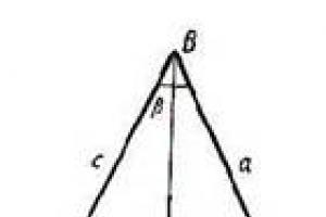
Consider an ordinary bar magnet: magnet 1 rests on the North surface with the pole up. Hanging distance y "role="presentation" style="position: relative;"> Y y "role="presentation" style="position: relative;"> y "role="presentation" style="position: relative;">Y above it (supported from side to side by a plastic tube) is a second, smaller bar magnet, magnet 2 , with the North pole facing down. The magnetic forces between them exceed gravity and keep magnet 2 suspended. Consider some material, material-X, which is moving towards the gap between two magnets with initial speed. v " role="presentation" style="position: relative;"> v v " role="presentation" style="position: relative;"> v "role="presentation" style="position: relative;">v ,
Is there a material, material-X , that will reduce the distance y "role="presentation" style="position: relative;"> Y y "role="presentation" style="position: relative;"> y "role="presentation" style="position: relative;">Y between two magnets, and pass through the gap without changing speed v " role="presentation" style="position: relative;"> v v " role="presentation" style="position: relative;"> v "role="presentation" style="position: relative;">v ?
Physics lover
such a strange question
Answers
jojo
The material you are looking for might be a superconductor. These materials have zero current resistance and thus can compensate for penetrating field lines in the first material layers. This phenomenon is called the Meissner effect and is the very definition of a superconducting state.
In your case there are plates between two magnets, this will definitely reduce y "role="presentation" style="position: relative;"> Y y "role="presentation" style="position: relative;"> y "role="presentation" style="position: relative;">Y ,
For speed:
Here, usually the eddy currents induced by the magnetic field result in a power loss defined as:
P = π 2 B p 2 d 2 f 2 6 k ρ D , " role="presentation"> P P = π 2 B p 2 d 2 f 2 6 k ρ D , " role="presentation"> P = π 2 B p 2 d 2 f 2 6 k ρ D , " role="presentation"> = π P = π 2 B p 2 d 2 f 2 6 k ρ D , " role="presentation"> P = π 2 B p 2 d 2 f 2 6 k ρ D , " role="presentation"> 2 P = π 2 B p 2 d 2 f 2 6 k ρ D , " role="presentation"> P = π 2 B p 2 d 2 f 2 6 k ρ D , " role="presentation"> IN P = π 2 B p 2 d 2 f 2 6 k ρ D , " role="presentation"> P = π 2 B p 2 d 2 f 2 6 k ρ D , " role="presentation"> 2 P = π 2 B p 2 d 2 f 2 6 k ρ D , " role="presentation"> P = π 2 B p 2 d 2 f 2 6 k ρ D , " role="presentation"> P P = π 2 B p 2 d 2 f 2 6 k ρ D , " role="presentation"> P = π 2 B p 2 d 2 f 2 6 k ρ D , " role="presentation"> d P = π 2 B p 2 d 2 f 2 6 k ρ D , " role="presentation"> P = π 2 B p 2 d 2 f 2 6 k ρ D , " role="presentation"> 2 P = π 2 B p 2 d 2 f 2 6 k ρ D , " role="presentation"> P = π 2 B p 2 d 2 f 2 6 k ρ D , " role="presentation"> e P = π 2 B p 2 d 2 f 2 6 k ρ D , " role="presentation"> P = π 2 B p 2 d 2 f 2 6 k ρ D , " role="presentation"> 2 P = π 2 B p 2 d 2 f 2 6 k ρ D , " role="presentation"> P = π 2 B p 2 d 2 f 2 6 k ρ D , " role="presentation"> 6k ρD P = π 2 B p 2 d 2 f 2 6 k ρ D , " role="presentation"> P = π 2 B p 2 d 2 f 2 6 k ρ D , " role="presentation"> , P = π 2 B p 2 d 2 f 2 6 k ρ D , " role="presentation"> P = π 2 B p 2 d 2 f 2 6 k ρ D , " role="presentation">p P = π 2 B p 2 d 2 f 2 6 k ρ D , " role="presentation">= P = π 2 B p 2 d 2 f 2 6 k ρ D , " role="presentation">π P = π 2 B p 2 d 2 f 2 6 k ρ D , " role="presentation">2 P = π 2 B p 2 d 2 f 2 6 k ρ D , " role="presentation">B P = π 2 B p 2 d 2 f 2 6 k ρ D , " role="presentation">p P = π 2 B p 2 d 2 f 2 6 k ρ D , " role="presentation">2 P = π 2 B p 2 d 2 f 2 6 k ρ D , " role="presentation">d P = π 2 B p 2 d 2 f 2 6 k ρ D , " role="presentation">2 P = π 2 B p 2 d 2 f 2 6 k ρ D , "role="presentation">e P = π 2 B p 2 d 2 f 2 6 k ρ D , " role="presentation">2 P = π 2 B p 2 d 2 f 2 6 k ρ D , " role="presentation">6 P = π 2 B p 2 d 2 f 2 6 k ρ D , "role="presentation">K P = π 2 B p 2 d 2 f 2 6 k ρ D , " role="presentation">ρ P = π 2 B p 2 d 2 f 2 6 k ρ D , " role="presentation">D P = π 2 B p 2 d 2 f 2 6 k ρ D , " role="presentation">,
since, however, a superconductor has zero resistance and is thus de facto
ρ = ∞ "role="presentation"> ρ = ∞ ρ = ∞ "role="presentation"> ρ = ∞ "role="presentation">ρ ρ = ∞ " role="presentation"> = ρ = ∞ "role="presentation">∞
none kinetic energy should not be lost, and thus the speed will remain unchanged.
There is just one problem:
A superconductor can only exist at a very low temperature, so it might not be possible in your machine... you would at least need a liquid nitrogen cooling system to cool it down.
Other than superconductors, I don't see any possible material, because if the material is a conductor, then you always have losses due to eddy currents (thus reducing v " role="presentation" style="position: relative;"> v v " role="presentation" style="position: relative;"> v "role="presentation" style="position: relative;">v) or the material is not a conductor (then y "role="presentation" style="position: relative;"> Y y "role="presentation" style="position: relative;"> y "role="presentation" style="position: relative;">Y will not decrease).
adamdport
Can this phenomenon be observed in a car or somewhere in an experiment?
jojo
The point, however, is that when a superconductor enters a magnetic field, the lines of force will deviate, which will involve work... so actually, it will cost some energy to enter the region between the two magnets. If the plate leaves the area after, the energy will be won back.
Lupercus
There are materials with very high magnetic permeability, such as the so-called µ-metal. They are used to make screens that weaken the Earth's magnetic field in the path of an electron beam in sensitive electron-optical devices.
Since your question merges two separate parts, I'll split it to look at each of them separately.
1. Static case: do the magnetic poles move closer to each other when a magnetic shielding plate is placed between them?
Mu-materials do not "kill" the magnetic field between your magnetic poles, but only deflect its direction, directing part of it into the metal shield. This will greatly change the field strength B " role="presentation" style="position: relative;"> IN B " role="presentation" style="position: relative;"> B " role="presentation" style="position: relative;"> on the screen surface, almost overwhelming its parallel components. This leads to a decrease in magnetic pressure p = B 2 8 π μ " role="presentation" style="position: relative;"> p= B p = B 2 8 π μ " role="presentation" style="position: relative;"> p = B 2 8 π μ " role="presentation" style="position: relative;"> 2 p = B 2 8 π μ " role="presentation" style="position: relative;"> p = B 2 8 π μ " role="presentation" style="position: relative;"> 8 pi p = B 2 8 π μ " role="presentation" style="position: relative;"> p = B 2 8 π μ " role="presentation" style="position: relative;"> μ p = B 2 8 π μ " role="presentation" style="position: relative;"> p = B 2 8 π μ " role="presentation" style="position: relative;">p p = B 2 8 π μ " role="presentation" style="position: relative;">== p = B 2 8 π μ " role="presentation" style="position: relative;">B p = B 2 8 π μ " role="presentation" style="position: relative;">2 p = B 2 8 π μ " role="presentation" style="position: relative;">8 p = B 2 8 π μ " role="presentation" style="position: relative;">π p = B 2 8 π μ " role="presentation" style="position: relative;">μ in close proximity to the screen surface. If this decrease in the magnetic field on the screen would significantly change the magnetic pressure at the location of the magnets, causing them to move? I'm afraid a more detailed calculation is needed here.
2. Plate movement: Is it possible that the speed of the shielding plate will not change?
Consider the following very simple and intuitive experiment: Take a copper pipe and hold it upright. Take a small magnet and let it fall into the pipe. The magnet falls: i) slowly and ii) at a uniform speed.
Your geometry can be made similar to that of a falling pipe: consider a column of magnets floating on top of each other, i.e. with paired poles, NN and SS. Now take a "multi-plate" shield made of parallel sheets held firmly in place on the same distance from each other (for example, a 2D comb). This world simulates several falling pipes in parallel.
If you now hold a column of magnets in a vertical direction and pull a multi-plate through them with a constant force (analogous to gravity), then you will achieve a constant speed mode - similar to the falling pipe experiment.
This suggests that a column of magnets or, more precisely, their magnetic field acts on the copper plates of a viscous medium:
M p l a t e v ˙ = − γ B v + F p u l l " role="presentation"> m m p l a t e v ˙ = − γ B v + F p u l l " role="presentation"> m p l a t e v ˙ = − γ B v + F p u l l " role="presentation"> p l a t e m p l a t e v ˙ = − γ B v + F p u l l " role="presentation"> m p l a t e v ˙ = − γ B v + F p u l l " role="presentation"> v m p l a t e v ˙ = − γ B v + F p u l l " role="presentation"> m p l a t e v ˙ = − γ B v + F p u l l " role="presentation"> ˙ m p l a t e v ˙ = − γ B v + F p u l l " role="presentation"> m p l a t e v ˙ = − γ B v + F p u l l " role="presentation"> = - γ m p l a t e v ˙ = − γ B v + F p u l l " role="presentation"> m p l a t e v ˙ = − γ B v + F p u l l " role="presentation"> IN m p l a t e v ˙ = − γ B v + F p u l l " role="presentation"> m p l a t e v ˙ = − γ B v + F p u l l " role="presentation"> V+ F m p l a t e v ˙ = − γ B v + F p u l l " role="presentation"> m p l a t e v ˙ = − γ B v + F p u l l " role="presentation"> p l l m p l a t e v ˙ = − γ B v + F p u l l " role="presentation"> m p l a t e v ˙ = − γ B v + F p u l l " role="presentation">m m p l a t e v ˙ = − γ B v + F p u l l " role="presentation">p m p l a t e v ˙ = − γ B v + F p u l l " role="presentation">L m p l a t e v ˙ = − γ B v + F p u l l " role="presentation">T m p l a t e v ˙ = − γ B v + F p u l l " role="presentation">e m p l a t e v ˙ = − γ B v + F p u l l " role="presentation">v m p l a t e v ˙ = − γ B v + F p u l l " role="presentation">˙ m p l a t e v ˙ = − γ B v + F p u l l " role="presentation"> = m p l a t e v ˙ = − γ B v + F p u l l " role="presentation">- m p l a t e v ˙ = − γ B v + F p u l l " role="presentation">γ m p l a t e v ˙ = − γ B v + F p u l l " role="presentation">В m p l a t e v ˙ = − γ B v + F p u l l " role="presentation">v m p l a t e v ˙ = − γ B v + F p u l l " role="presentation">+ m p l a t e v ˙ = − γ B v + F p u l l " role="presentation">F m p l a t e v ˙ = − γ B v + F p u l l " role="presentation">p m p l a t e v ˙ = − γ B v + F p u l l " role="presentation">U m p l a t e v ˙ = − γ B v + F p u l l " role="presentation">L m p l a t e v ˙ = − γ B v + F p u l l " role="presentation">L
Where γ B " role="presentation" style="position: relative;"> γ γ B " role="presentation" style="position: relative;"> γ B " role="presentation" style="position: relative;"> IN γ B " role="presentation" style="position: relative;"> γ B " role="presentation" style="position: relative;">γ γ B "role="presentation" style="position: relative;">B will be the effective coefficient of friction due to the magnetic field perturbed by the presence of the plates. After a while, you will eventually reach a regime in which the friction force will compensate for your effort, and the speed will remain constant: v = F p u l l γ B " role="presentation" style="position: relative;"> v= F v = F p u l l γ B " role="presentation" style="position: relative;"> v = F p u l l γ B " role="presentation" style="position: relative;"> p l l v = F p u l l γ B " role="presentation" style="position: relative;"> v = F p u l l γ B " role="presentation" style="position: relative;"> γ v = F p u l l γ B " role="presentation" style="position: relative;"> v = F p u l l γ B " role="presentation" style="position: relative;"> IN v = F p u l l γ B " role="presentation" style="position: relative;"> v = F p u l l γ B " role="presentation" style="position: relative;"> v v = F p u l l γ B " role="presentation" style="position: relative;"> = v = F p u l l γ B " role="presentation" style="position: relative;"> F v = F p u l l γ B " role="presentation" style="position: relative;"> P v = F p u l l γ B " role="presentation" style="position: relative;"> U v = F p u l l γ B " role="presentation" style="position: relative;"> L v = F p u l l γ B " role="presentation" style="position: relative;"> L v = F p u l l γ B " role="presentation" style="position: relative;"> γ v = F p u l l γ B " role="presentation" style="position: relative;"> IN ,
If this speed is equal to the speed you had before you pulled the plates into the magnetic field, it's a matter of how you control the force of attraction. Note: if there is no traction, then the plate will simply be stopped by the magnetic brake effect. So you have to pull accordingly if you want to have a constant speed.
How can I make two magnets next to each other not feel each other's presence? What material should be placed between them so that the magnetic field lines from one magnet would not reach the second magnet?
This question is not as trivial as it might seem at first glance. We need to really isolate the two magnets. That is, so that these two magnets can be rotated in different ways and moved in different ways relative to each other, and yet each of these magnets behaves as if there is no other magnet nearby. Therefore, any tricks with the placement of a third magnet or a ferromagnet next to it, to create some special configuration of magnetic fields with compensation for all magnetic fields at one single point, fundamentally do not work.
Diamagnet???
Sometimes it is mistakenly thought that such an insulator of the magnetic field can serve as diamagnetic. But this is not true. A diamagnet actually weakens the magnetic field. But it weakens the magnetic field only in the thickness of the diamagnet itself, inside the diamagnet. Because of this, many mistakenly think that if one or both magnets are walled up in a piece of diamagnet, then, allegedly, their attraction or their repulsion will weaken.
But this is not a solution to the problem. Firstly, the lines of force of one magnet will still reach another magnet, that is, the magnetic field only decreases in the thickness of the diamagnet, but does not disappear completely. Secondly, if the magnets are walled up in the thickness of the diamagnet, then we cannot move and rotate them relative to each other.
And if you make just a flat screen out of a diamagnet, then this screen will let the magnetic field through itself. Moreover, behind this screen the magnetic field will be exactly the same as if this diamagnetic screen did not exist at all.
This suggests that even magnets immured in a diamagnet will not experience the weakening of each other's magnetic field. Indeed, where there is a walled-in magnet, there is simply no diamagnet right in the volume of this magnet. And since there is no diamagnet where the imbedded magnet is located, it means that both immured magnets actually interact with each other in the same way as if they were not immured in a diamagnet. The diamagnet around these magnets is just as useless as the flat diamagnetic screen between the magnets.
Ideal diamagnet
We need a material that, in general, would not pass through itself the lines of force of the magnetic field. It is necessary that the lines of force of the magnetic field are pushed out of such a material. If the lines of force of the magnetic field pass through the material, then, behind a screen of such material, they fully restore all their strength. This follows from the law of conservation of magnetic flux.
In a diamagnet, the weakening of the external magnetic field occurs due to the induced internal magnetic field. This induced magnetic field is created by circular currents of electrons inside the atoms. When an external magnetic field is turned on, the electrons in the atoms must begin to move around the lines of force of the external magnetic field. This induced circular motion of electrons in atoms creates an additional magnetic field, which is always directed against the external magnetic field. Therefore, the total magnetic field inside the diamagnet becomes smaller than outside.
But there is no complete compensation of the external field due to the induced internal field. There is not enough strength of the circular current in the atoms of the diamagnet to create exactly the same magnetic field as the external magnetic field. Therefore, the lines of force of the external magnetic field remain in the thickness of the diamagnet. The external magnetic field, as it were, "pierces" the material of the diamagnet through and through.
The only material that pushes out magnetic field lines is a superconductor. In a superconductor, an external magnetic field induces such circular currents around the lines of force of the external field that create an oppositely directed magnetic field exactly equal to the external magnetic field. In this sense, a superconductor is an ideal diamagnet.

On the surface of a superconductor, the magnetic field vector is always directed along this surface, tangential to the surface of the superconducting body. On the surface of a superconductor, the magnetic field vector does not have a component directed perpendicular to the surface of the superconductor. Therefore, the lines of force of the magnetic field always go around a superconducting body of any shape.
Bending around a superconductor by magnetic field lines
But this does not mean at all that if a superconducting screen is placed between two magnets, then it will solve the problem. The fact is that the lines of force of the magnetic field of the magnet will go to another magnet, bypassing the screen from the superconductor. Therefore, from a flat superconducting screen, there will only be a weakening of the influence of magnets on each other.
This weakening of the interaction of the two magnets will depend on how much the length of the field line that connects the two magnets to each other has increased. The greater the length of the connecting lines of force, the less the interaction of the two magnets with each other.
This is exactly the same effect as if you increase the distance between the magnets without any superconducting screen. If you increase the distance between the magnets, then the length of the magnetic field lines also increase.
This means that in order to increase the length of the lines of force that connect two magnets bypassing the superconducting screen, it is necessary to increase the dimensions of this flat screen both in length and in width. This will lead to an increase in the lengths of bypassing field lines. And the larger the dimensions of the flat screen compared to the distance between the magnets, the smaller the interaction between the magnets becomes.
The interaction between the magnets completely disappears only when both dimensions of the flat superconducting screen become infinite. This is analogous to the situation when the magnets were separated to an infinitely large distance, and therefore the length of the magnetic field lines connecting them became infinite.
Theoretically, this, of course, completely solves the problem. But in practice, we cannot make a superconducting flat screen of infinite dimensions. I would like to have a solution that can be put into practice in the laboratory or in production. (We are no longer talking about everyday conditions, since it is impossible to make a superconductor in everyday life.)
Division of space by a superconductor
In another way, a flat screen of infinite dimensions can be interpreted as a divider of the entire three-dimensional space into two parts that are not connected to each other. But space can be divided into two parts not only by a flat screen of infinite dimensions. Any closed surface also divides space into two parts, into the volume inside the closed surface and the volume outside the closed surface. For example, any sphere divides space into two parts: a ball inside the sphere and everything outside.
Therefore, the superconducting sphere is an ideal magnetic field insulator. If a magnet is placed in such a superconducting sphere, then no instruments can ever detect whether there is a magnet inside this sphere or not.
And, conversely, if you are placed inside such a sphere, then external magnetic fields will not act on you. For example, the Earth's magnetic field will be impossible to detect inside such a superconducting sphere by any instruments. Inside such a superconducting sphere, it will be possible to detect only the magnetic field from those magnets that will also be located inside this sphere.
Thus, in order for two magnets not to interact with each other, one of these magnets must be placed inside the superconducting sphere, and the other left outside. Then the magnetic field of the first magnet will be completely concentrated inside the sphere and will not go beyond this sphere. Therefore, the second magnet will not feel welcomed by the first. Similarly, the magnetic field of the second magnet will not be able to climb inside the superconducting sphere. And so the first magnet will not feel the close presence of the second magnet.
Finally, we can rotate and move both magnets in any way relative to each other. True, the first magnet is limited in its movements by the radius of the superconducting sphere. But that's just how it seems. In fact, the interaction of two magnets depends only on their relative position and their rotations around the center of gravity of the corresponding magnet. Therefore, it is enough to place the center of gravity of the first magnet in the center of the sphere and place the origin of coordinates in the same place in the center of the sphere. All possible options for the location of the magnets will be determined only by all possible options the location of the second magnet relative to the first magnet and their angles of rotation around their centers of mass.
Of course, instead of a sphere, you can take any other shape of the surface, for example, an ellipsoid or a surface in the form of a box, etc. If only she divided the space into two parts. That is, in this surface there should not be a hole through which a line of force can crawl through, which will connect the inner and outer magnets.
Shielding of magnetic fields can be carried out in two ways:
Shielding with ferromagnetic materials.
Shielding with eddy currents.
The first method is usually used for screening constant MF and low frequency fields. The second method provides significant efficiency in shielding high frequency MF. Due to the surface effect, the density of eddy currents and the intensity of the alternating magnetic field, as they go deeper into the metal, fall according to an exponential law:
The reduction in field and current, which is called the equivalent penetration depth.
The smaller the penetration depth, the greater the current flows in the surface layers of the screen, the greater the reverse MF created by it, which displaces the external field of the pickup source from the space occupied by the screen. If the shield is made of a non-magnetic material, then the shielding effect will depend only on the specific conductivity of the material and the frequency of the shielding field. If the screen is made of a ferromagnetic material, then, other things being equal, a large e will be induced in it by an external field. d.s. due to the greater concentration of magnetic field lines. With the same conductivity of the material, eddy currents will increase, resulting in a smaller penetration depth and a better shielding effect.
When choosing the thickness and material of the screen, one should proceed not from the electrical properties of the material, but be guided by considerations of mechanical strength, weight, rigidity, resistance to corrosion, ease of joining individual parts and making transitional contacts between them with low resistance, ease of soldering, welding, and so on.
It can be seen from the data in the table that for frequencies above 10 MHz, copper and even more so silver films with a thickness of about 0.1 mm give a significant shielding effect. Therefore, at frequencies above 10 MHz, it is quite acceptable to use screens made of foil-coated getinax or fiberglass. At high frequencies, steel gives a greater shielding effect than non-magnetic metals. However, it should be taken into account that such screens can introduce significant losses into the shielded circuits due to high resistivity and hysteresis. Therefore, such screens are applicable only in cases where insertion loss can be ignored. Also, for greater shielding efficiency, the screen must have less magnetic resistance than air, then the magnetic field lines tend to pass along the walls of the screen and penetrate into the space outside the screen in a smaller number. Such a screen is equally suitable for protection against the effects of a magnetic field and for protecting the external space from the influence of a magnetic field created by a source inside the screen.
There are many grades of steel and permalloy with different values of magnetic permeability, so for each material it is necessary to calculate the value of the penetration depth. The calculation is made according to the approximate equation:
![]()
1) Protection against external magnetic field

The magnetic lines of force of the external magnetic field (the lines of induction of the magnetic interference field) will pass mainly through the thickness of the walls of the screen, which has a low magnetic resistance compared to the resistance of the space inside the screen. As a result, the external magnetic interference field will not affect the operation of the electrical circuit.
2) Shielding of own magnetic field

Such craneing is used if the task is to protect external electrical circuits from the effects of a magnetic field created by the coil current. Inductance L, i.e., when it is required to practically localize the interference created by the inductance L, then such a problem is solved using a magnetic screen, as shown schematically in the figure. Here, almost all field lines of the field of the inductor will close through the thickness of the screen walls, without going beyond them due to the fact that the magnetic resistance of the screen is much less than the resistance of the surrounding space.
3) Dual screen
In a double magnetic screen, one can imagine that part of the magnetic lines of force, which go beyond the thickness of the walls of one screen, will close through the thickness of the walls of the second screen. In the same way, one can imagine the action of a double magnetic screen when localizing magnetic interference created by an electrical circuit element located inside the first (inner) screen: the bulk of the magnetic lines of force (magnetic stray lines) will close through the walls of the outer screen. Of course, in double screens, the wall thicknesses and the distance between them must be rationally chosen.
Overall coefficient shielding reaches its greatest value in those cases when the wall thickness and the gap between the screens increase in proportion to the distance from the center of the screen, and the size of the gap is the geometric mean of the wall thicknesses of the screens adjacent to it. In this case, the shielding factor:
L = 20lg (H/Ne)
The manufacture of double screens in accordance with this recommendation is practically difficult for technological reasons. It is much more expedient to choose the distance between the shells adjacent to the air gap of the screens, greater than the thickness of the first screen, approximately equal to the distance between the steak of the first screen and the edge of the shielded circuit element (for example, coils and inductors). The choice of one or another wall thickness of the magnetic screen cannot be made unambiguous. Rational wall thickness is determined. shield material, interference frequency and specified shielding factor. It is useful to take into account the following.
1. With an increase in the frequency of interference (frequency of an alternating magnetic field of interference), the magnetic permeability of materials decreases and causes a decrease in the shielding properties of these materials, since as the magnetic permeability decreases, the resistance to magnetic flux exerted by the screen increases. As a rule, the decrease in magnetic permeability with increasing frequency is most intense for those magnetic materials that have the highest initial magnetic permeability. For example, sheet electrical steel with a low initial magnetic permeability changes the value of jx little with increasing frequency, and permalloy, which has high initial values of the magnetic permeability, is very sensitive to an increase in the frequency of the magnetic field; its magnetic permeability drops sharply with frequency.
2. In magnetic materials exposed to a high-frequency magnetic interference field, the surface effect is noticeably manifested, i.e., the displacement of the magnetic flux to the surface of the screen walls, causing an increase in the magnetic resistance of the screen. Under such conditions, it seems almost useless to increase the thickness of the screen walls beyond the limits occupied by the magnetic flux at a given frequency. Such a conclusion is incorrect, because an increase in the wall thickness leads to a decrease in the magnetic resistance of the screen even in the presence of a surface effect. At the same time, the change in magnetic permeability should also be taken into account. Since the phenomenon of the skin effect in magnetic materials usually becomes more noticeable than the decrease in magnetic permeability in the low-frequency region, the influence of both factors on the choice of screen wall thickness will be different in different ranges of magnetic interference frequencies. As a rule, the decrease in shielding properties with increasing interference frequency is more pronounced in shields made of materials with a high initial magnetic permeability. The above features of magnetic materials provide the basis for recommendations on the choice of materials and wall thicknesses of magnetic screens. These recommendations can be summarized as follows:
A) screens made of ordinary electrical (transformer) steel, which have a low initial magnetic permeability, can be used, if necessary, to provide small screening factors (Ke 10); such screens provide an almost constant screening factor in a fairly wide frequency band, up to several tens of kilohertz; the thickness of such screens depends on the frequency of interference, and the lower the frequency, the greater the thickness of the screen required; for example, at a frequency of a magnetic interference field of 50-100 Hz, the thickness of the screen walls should be approximately equal to 2 mm; if an increase in the shielding factor or a greater thickness of the shield is required, then it is advisable to use several shielding layers (double or triple shields) of smaller thickness;
B) it is advisable to use screens made of magnetic materials with high initial permeability (for example, permalloy) if it is necessary to provide a large screening factor (Ke > 10) in a relatively narrow frequency band, and it is not advisable to choose a thickness of each magnetic screen shell greater than 0.3-0.4 mm; the shielding effect of such screens begins to drop noticeably at frequencies above several hundred or thousand hertz, depending on the initial permeability of these materials.
Everything said above about magnetic shields is true for weak magnetic interference fields. If the screen is located near powerful sources of interference and there are magnetic fluxes with a large magnetic induction, then, as you know, it is necessary to take into account the change in magnetic dynamic permeability depending on the induction; it is also necessary to take into account the losses in the thickness of the screen. In practice, such strong sources of magnetic interference fields, in which one would have to take into account their effect on screens, are not encountered, with the exception of some special cases that do not provide for amateur radio practice and normal operating conditions for radio engineering devices of wide application.
Test
1. With magnetic shielding, the shield must:
1) Possess less magnetic resistance than air
2) have magnetic resistance equal to air
3) have greater magnetic resistance than air
2. When shielding the magnetic field Grounding the shield:
1) Does not affect shielding efficiency
2) Increases the effectiveness of magnetic shielding
3) Reduces the effectiveness of magnetic shielding
3. At low frequencies (<100кГц) эффективность магнитного экранирования зависит от:
a) Shield thickness, b) Magnetic permeability of the material, c) Distance between the shield and other magnetic circuits.
1) Only a and b are true
2) Only b and c are true
3) Only a and b are true
4) All options are correct
4. Magnetic shielding at low frequencies uses:
1) Copper
2) Aluminum
3) Permalloy.
5. Magnetic shielding at high frequencies uses:
1) Iron
2) Permalloy
3) Copper
6. At high frequencies (>100 kHz), the effectiveness of magnetic shielding does not depend on:
1) Screen thickness
2) Magnetic permeability of the material
3) Distances between the screen and other magnetic circuits.
Used literature:
2. Semenenko, V. A. Information Security/ V. A. Semenenko - Moscow, 2008
3. Yarochkin, V. I. Information security / V. I. Yarochkin - Moscow, 2000.
4. Demirchan, K. S. Theoretical basis Electrical Engineering Volume III / K. S. Demirchan S.-P, 2003