« Physics - Grade 10 "
angular acceleration.
Previously, we obtained a formula relating the linear velocity υ, the angular velocity ω and the radius R of the circle along which the selected element (material point) of an absolutely rigid body moves, which rotates about a fixed axis:
We know that linear the velocities and accelerations of the points of a rigid body are different. In the same time angular velocity all points of a rigid body is the same.
Angular velocity is a vector quantity. The direction of the angular velocity is determined by the gimlet rule. If the direction of rotation of the handle of the gimlet coincides with the direction of rotation of the body, then the translational movement of the gimlet indicates the direction of the angular velocity vector (Fig. 6.1).
However, uniform rotational motion is quite rare. Much more often we are dealing with a movement in which the angular velocity changes, obviously, this occurs at the beginning and end of the movement.
The reason for the change in the angular velocity of rotation is the action of forces on the body. The change in angular velocity with time determines angular acceleration.
The angular velocity vector is a sliding vector. Regardless of the point of application, its direction indicates the direction of rotation of the body, and the module determines the speed of rotation,
The average angular acceleration is equal to the ratio of the change in angular velocity to the time interval during which this change occurred:
At uniformly accelerated motion the angular acceleration is constant and, with a fixed axis of rotation, characterizes the change in the angular velocity in absolute value. With an increase in the angular velocity of rotation of the body, the angular acceleration is directed in the same direction as the angular velocity (Fig. 6.2, a), and with a decrease, in the opposite direction (Fig. 6.2, b).

Since the angular velocity is related to the linear velocity by the relation υ = ωR, the change in the linear velocity over a certain period of time Δt is equal to Δυ = ΔωR. Dividing the left and right sides of the equation by Δt, we have or a = εR, where a is tangent(linear) acceleration, directed tangentially to the trajectory of motion (circle).
If time is measured in seconds, and angular velocity is in radians per second, then one unit of angular acceleration is equal to 1 rad / s 2, i.e. angular acceleration is expressed in radians per second squared.
Any rotating bodies move unevenly when starting and stopping, for example, a rotor in an electric motor, a lathe disk, a car wheel during acceleration, etc.
Moment of power.
For creating rotary motion not only the value of the force is important, but also the point of its application. It is very difficult to open the door by applying pressure near the hinges, but at the same time you can easily open it by pressing on the door as far as possible from the axis of rotation, for example, on the handle. Consequently, for rotational motion, not only the value of the force is essential, but also the distance from the axis of rotation to the point of application of the force. In addition, the direction of the applied force is also important. You can pull the wheel with a lot of force, but still not cause it to rotate.
The moment of force is a physical quantity equal to the product of the force and the shoulder:

M = Fd,
where d is the shoulder of the force, equal to the shortest distance from the axis of rotation to the line of action of the force (Fig. 6.3).
Obviously, the moment of force is maximum if the force is perpendicular to the radius vector drawn from the axis of rotation to the point of application of this force.
If several forces act on the body, then the total moment is equal to algebraic sum moments of each of the forces about a given axis of rotation.

In this case, the moments of forces that cause the rotation of the body counterclockwise, we will consider positive(force 2), and the moments of forces causing clockwise rotation - negative(forces 1 and 3) (Fig. 6.4).
The basic equation of the dynamics of rotational motion. Just as it was experimentally shown that the acceleration of a body is directly proportional to the force acting on it, it was found that the angular acceleration is directly proportional to the moment of force:

Let a force act on a material point moving along a circle (Fig. 6.5). According to Newton's second law, in the projection onto the tangent direction, we have ma k \u003d F k. Multiplying the left and right sides of the equation by r, we get ma k r \u003d F k r, or
mr 2 ε = M. (6.1)
Note that in this case r is the shortest distance from the axis of rotation to material point and, accordingly, the point of application of force.
The product of the mass of a material point and the square of the distance to the axis of rotation is called moment of inertia of a material point and denoted by the letter I.
Thus, equation (6.1) can be written as I ε = M, whence
Equation (6.2) is called the basic equation of the dynamics of rotational motion.
Equation (6.2) is also valid for rotational motion solid body having a fixed axis of rotation, where I is the moment of inertia of the rigid body, and M is the total moment of forces acting on the body. In this chapter, when calculating the total moment of forces, we consider only forces or their projections belonging to a plane perpendicular to the axis of rotation.
The angular acceleration with which a body rotates is directly proportional to the sum of the moments of forces acting on it, and inversely proportional to the moment of inertia of the body about a given axis of rotation.

If the system consists of a set of material points (Fig. 6.6), then the moment of inertia of this system relative to a given axis of rotation OO "is equal to the sum of the moments of inertia of each material point relative to this axis of rotation: I \u003d m 1 r 2 1 + m 2 r 2 2 + ... .
The moment of inertia of a rigid body can be calculated by dividing the body into small volumes, which can be considered material points, and summing up their moments of inertia about the axis of rotation. Obviously, the moment of inertia depends on the position of the axis of rotation.
From the definition of the moment of inertia it follows that the moment of inertia characterizes the distribution of mass relative to the axis of rotation.
Let us present the values of the moments of inertia for some absolutely rigid homogeneous bodies of mass m.

1. Moment of inertia of thin straight rod length l relative to the axis perpendicular to the rod and passing through its middle (Fig. 6.7) is equal to:
2. Moment of inertia straight cylinder(Fig. 6.8), or a disk relative to the OO axis, which coincides with the geometric axis of the cylinder or disk:
3. Moment of inertia ball
4. Moment of inertia thin hoop radius R relative to the axis passing through its center:
moment of inertia physical meaning in rotational motion it plays the role of mass, i.e., it characterizes the inertia of the body with respect to rotational motion. The greater the moment of inertia, the more difficult it is to make the body rotate or, conversely, to stop the rotating body.
Let some body, under the action of a force F applied at point A, come into rotation around the axis OO" (Fig. 1.14).
The force acts in a plane perpendicular to the axis. The perpendicular p, dropped from the point O (lying on the axis) to the direction of the force, is called shoulder of strength. The product of the force on the shoulder determines the modulus of the moment of force relative to the point O:
M = Fp=Frsinα.
Moment of power is a vector determined by the vector product of the radius-vector of the force application point and the force vector:
 (3.1) The unit of the moment of force is the newton meter (N m).
The direction of M can be found using the right screw rule.
angular momentum particle is called the vector product of the radius vector of the particle and its momentum:
 or in scalar form L = gPsinα
This quantity is vector and coincides in direction with the vectors ω.
§ 3.2 Moment of inertia. Steiner's theorem
A measure of the inertia of bodies in translational motion is the mass. The inertia of bodies during rotational motion depends not only on the mass, but also on its distribution in space relative to the axis of rotation. The measure of inertia during rotational motion is a quantity calledmoment of inertia of the body about the axis of rotation.
The moment of inertia of a material point relative to the axis of rotation is the product of the mass of this point and the square of its distance from the axis:
I i =m i r i 2 (3.2)
Moment of inertia of the body about the axis of rotation call the sum of the moments of inertia of the material points that make up this body:
 (3.3)
(3.3)
In the general case, if the body is solid and is a collection of points with small masses dm, the moment of inertia is determined by integration:
 (3.4)
(3.4)
If the body is homogeneous and its density  , then the moment of inertia of the body
 (3.5)
(3.5)
The moment of inertia of a body depends on which axis it rotates and how the mass of the body is distributed throughout the volume.
The moment of inertia of bodies that have the correct geometric shape and a uniform distribution of mass over volume is most simply determined.
Moment of inertia of a homogeneous rod relative to the axis passing through the center of inertia and perpendicular to the rod
 (3.6)
(3.6)
Moment of inertia of a homogeneous cylinder about an axis perpendicular to its base and passing through the center of inertia,
 (3.7)
(3.7)
Moment of inertia of a thin-walled cylinder or a hoop about an axis perpendicular to the plane of its base and passing through its center,
 (3.8)
(3.8)
Moment of inertia ball relative to diameter
 (3.9)
(3.9)
Consider an example . Let us determine the moment of inertia of the disk about the axis passing through the center of inertia and perpendicular to the plane of rotation. Disk mass - m, radius - R.
The area of the ring (Fig. 3.2), enclosed between
r and r + dr is equal to dS = 2πr dr . Disk area S = πR 2 .
Hence,  . Then
 or
or 
According to
The above formulas for the moments of inertia of bodies are given under the condition that the axis of rotation passes through the center of inertia. To determine the moments of inertia of a body about an arbitrary axis, one should use Steiner's theorem : the moment of inertia of the body about an arbitrary axis of rotation is equal to the sum of the moment of inertia of the body about an axis parallel to the given one and passing through the center of mass of the body, and the product of the body's mass by the square of the distance between the axes:
 (3.11)
The unit of the moment of inertia is a kilogram-meter squared (kg m 2).
So, the moment of inertia of a homogeneous rod about the axis passing through its end, according to Steiner's theorem, is equal to
 (3.12)
4.6 Rotational motion of a rigid body. Moment of power.
Of course, the position of one, even “special”, point does not completely describe the movement of the entire system of bodies under consideration, but still, it is better to know the position of at least one point than not to know anything. However, consider the application of Newton's laws to the description of rotation solid body around a fixed axis.
Let's start with the simplest case: let the material point of the mass m attached with a weightless rigid rod of length r to the fixed axis OO'(Fig. 46). A material point can move around the axis, remaining at a constant distance from it, therefore, its trajectory will be a circle centered on the axis of rotation.
Of course, the motion of a point obeys the equation of Newton's second law \(~m \vec a = \vec F_0\). However, the direct application of this equation is not justified: firstly, the point has one degree of freedom, so it is convenient to use the rotation angle as the only coordinate, and not two Cartesian coordinates; secondly, the reaction forces in the axis of rotation act on the system under consideration, and directly on the material point - the tension force of the rod. Finding these forces is a separate problem, the solution of which is redundant for describing rotation. Therefore, it makes sense to obtain, on the basis of Newton's laws, a special equation that directly describes the rotational motion.
Let some force \(~\vec F\) act on a material point at some point in time, lying in a plane perpendicular to the axis of rotation (Fig. 47). In the kinematic description of the curvilinear motion, the total acceleration vector \(~\vec a\) is conveniently decomposed into two components: the normal \(~\vec a_n\), directed to the axis of rotation, and the tangential \(~\vec a_(\tau)\ ) directed parallel to the velocity vector. We do not need the value of normal acceleration to determine the law of motion. Of course, this acceleration is also due to acting forces, one of which is the unknown tensile force of the rod.

Let us write the equation of the second law in the projection onto the tangential direction:
\(~m a_(\tau) = F_(\tau)\) , (1)
note that the reaction force of the rod is not included in this equation, since it is directed along the rod and perpendicular to the selected projection. Changing the angle of rotation φ is directly determined by the angular velocity \(~\omega = \frac(\Delta \varphi)(\Delta t)\) , whose change is in turn described by the angular acceleration \(~\varepsilon = \frac(\Delta \omega)(\ Delta t)\) . Angular acceleration is related to the tangential acceleration component by the relation a τ = rε. If we substitute this expression into equation (9), we obtain an equation suitable for determining the angular acceleration. It is convenient to introduce a new physical quantity that determines the interaction of bodies during their rotation. To do this, we multiply both sides of equation (1) by r
\(~m r^2 \varepsilon = F_(\tau) r\) . (2)
and consider the expression on its right side F τ r, which has the meaning of the product of the tangential component of the force, by the distance from the axis of rotation to the point of application of the force. The same work can be represented in a slightly different form (see Fig. 48)

M = F τ r = Fr cos α = fd, Here d- the distance from the axis of rotation to the line of action of the force, which is also called shoulder of strength. This physical quantity the product of the modulus of force and the distance from the line of action of the force to the axis of rotation (shoulder of the force) M = fd called moment of force. The action of a force can lead to rotation, both clockwise and counterclockwise. In accordance with the chosen positive direction of rotation, the sign of the moment of force should also be determined. Note that the moment of force is determined by the component of the force that is perpendicular to the radius vector of the point of application. The component of the force vector directed along the segment connecting the point of application and the axis of rotation does not lead to untwisting of the body. This component, when the axis is fixed, is compensated by the reaction force in the axis, so it does not affect the rotation of the body.

Let's write down one more useful expression for the moment of force. Let the force \(~\vec F\) be applied to the point A , whose Cartesian coordinates are x,y(Fig. 49). Let us decompose the force \(~\vec F\) into two components \(~\vec F_x, \vec F_y\) , parallel to the corresponding coordinate axes. The moment of force \(~\vec F\) about the axis passing through the origin is obviously equal to the sum of the moments of the components \(~\vec F_x, \vec F_y\) , that is, M = xF y- yF x .

Similarly, to the way we introduced the concept of the angular velocity vector, we can also define the concept of the vector of the moment of force. The module of this vector corresponds to the definition given above, but it is directed perpendicular to the plane containing the force vector and the segment connecting the point of application of the force with the axis of rotation. The vector of the moment of force can also be defined as the vector product of the radius vector of the point of application of the force and the force vector
\(~\vec M = \vec r \times \vec F\) .
Note that when the point of application of force is displaced along the line of its action, the moment of force does not change.
Let us denote the product of the mass of a material point by the square of the distance to the axis of rotation mr 2 = I(this value is called moment of inertia of a material point about the axis). Using these notations, equation (2) takes the form that formally coincides with the equation of Newton's second law for translational motion
\(~I \varepsilon = M\) . (3)
This equation is called the basic equation of rotational motion dynamics. So, the moment of force in rotational motion plays the same role as the force in translational motion, it is he who determines the change in angular velocity. It turns out that (and this is confirmed by our everyday experience) the influence of force on the speed of rotation is determined not only by the magnitude of the force, but also by the point of its application. The moment of inertia determines the inertial properties of the body in relation to rotation (in simple terms, it shows whether it is easy to spin the body) - the farther from the axis of rotation a material point is, the more difficult it is to bring it into rotation.
Equation (3) can be generalized to the case of rotation of an arbitrary body. When a body rotates around a fixed axis, the angular accelerations of all points of the body are the same. Therefore, just as we did when deriving Newton's equation for the translational motion of a body, we can write equations (3) for all points of a rotating body and then sum them up. As a result, we obtain an equation that outwardly coincides with (3), in which I- the moment of inertia of the whole body, equal to the sum of the moments of its constituent material points, M- sum of moments external forces acting on the body.

Let us show how the moment of inertia of a body is calculated. It is important to emphasize that the moment of inertia of a body depends not only on the mass, shape and dimensions of the body, but also on the position and orientation of the axis of rotation. Formally, the calculation procedure is reduced to dividing the body into small parts, which can be considered material points (Fig. 51), and summing the moments of inertia of these material points, which are equal to the product of the mass by the square of the distance to the axis of rotation
\(~I = m_1 r^2_1 + m_2 r^2_2 + m_3 r^2_3 + \ldots\) .
For bodies of a simple shape, such sums have long been calculated, so it is often enough to remember (or find in a reference book) the appropriate formula for the desired moment of inertia. As an example: the moment of inertia of a circular homogeneous cylinder of mass m and radius R for the axis of rotation coinciding with the axis of the cylinder is equal to \(~I = \frac(1)(2) m R^2\) .
When observing complex movements, such as the movement of the human body (walking, running, jumping, etc.), it seems difficult or even impossible to describe the movement of all its points. However, analyzing such movements, one can notice that they consist of simpler translational and rotational movements.
The mechanics of translational motion is known to the reader, so the section begins with a consideration of rotational motion. The simplest is the rotation of a rigid body around a fixed axis. This case allows you to get acquainted with the specifics, terminology and laws of rotational motion.
5.1. KINEMATICS OF ROTATIONAL MOTION OF A ABSOLUTELY RIGID BODY AROUND A FIXED AXIS
An absolutely rigid body is one whose distance between any two points is constant.
The dimensions and shape of an absolutely rigid body do not change when it moves.
The concept of "absolutely rigid body" is a physical abstraction, since any body is capable of deformation. However, in many cases the deformation can be neglected.
The simplest case of rotational motion of an absolutely rigid body is rotation about a fixed axis. This is such a movement in which the points of the body move along circles, the centers of which lie on a straight line, called the axis of rotation.
It is known that in some cases, to characterize the motion of a body, it is not necessary to indicate the motion of all its points; so, for example, in translational motion it is sufficient to indicate the motion of any one point of the body.
During rotational motion around the axis, the points of the body move along different trajectories, but at the same time, all points and the body itself rotate through the same angle. To characterize the rotation
draw in a plane perpendicular to the axis, the radius vector to some point i(Fig. 5.1). The time dependence of the angle α of rotation of the radius-vector relative to some selected direction OX is the equation for the rotational motion of a rigid body around a fixed axis:
The speed of rotation of the body is characterized by an angular velocity equal to the first derivative of the angle of rotation of the radius-vector with respect to time:
The angular velocity is a vector that is directed along the axis of rotation and is related to the direction of rotation by the rule of the right screw (Fig. 5.2). The angular velocity vector, unlike the velocity and force vectors, is sliding: it does not have a specific application point, and it can be located anywhere on the rotation axis. Thus, setting the vector ω indicates the position of the axis of rotation, the direction of rotation and the modulus of the angular velocity.

The rate of change of the angular velocity is characterized by an angular acceleration equal to the first derivative of the angular velocity with respect to time:
or in vector form:
It can be seen from (5.4) that the angular acceleration vector coincides in direction with an elementary, sufficiently small change in the angular velocity vector dω : with accelerated rotation, the angular acceleration is directed in the same way as the angular velocity, with slow rotation, it is opposite to it.
Since the angular displacement of all points of an absolutely rigid body is the same, then, according to (5.2) and (5.3), at the same time all points of the body have the same angular velocity and the same angular acceleration. Linear characteristics - movement, speed, acceleration - are different for different points. Let us indicate in scalar form the relationship, which can be derived independently, between the linear and angular characteristics for the i-th point moving along a circle with a radius ri:

Rice. 5.3

In conclusion, we present the formulas for the kinematics of the rotational motion of a rigid body around a fixed axis obtained by integrating the corresponding expressions:
equation of uniform rotational motion[cm. (5.2)]:
dependence of angular velocity on time in uniform rotational motion[cm. (5.3)]:
equation of uniform rotational motion[cm. (5.1) and (5.6)]:
It is useful to compare these formulas with similar dependencies for translational motion.
5.2. BASIC CONCEPTS. EQUATION OF DYNAMICS OF ROTATIONAL MOTION
Moment of power _
Let to some point i force applied to a rigid body F^, lying in a plane perpendicular to the axis of rotation (Fig. 5.4).
The moment of force about the axis of rotation is the vector product of the radius vector of the point i and the force:
Expanding it, you can write:
Where β - angle between vectors r i And F i . Since the shoulder of strength h i = r i sinβ (see Fig. 5.4), then
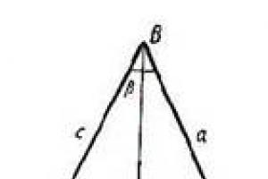
If the force acts at a certain angle α to the plane of rotation (Fig. 5.5), then it can be decomposed into two components. One of them lies in a plane perpendicular to the axis of rotation, and the other is parallel to this axis and does not affect the rotation of the body (in the real case, it only affects the bearings). In what follows, only forces lying in a plane perpendicular to the axis of rotation will be considered.

Rice. 5.4
Rice. 5.5
Work in rotary motion
Let under the action of force F i(see Fig. 5.4) the body rotates through a sufficiently small angle dα. Let's find the work of this force.
known from high school the expression for the work of the force in this case should be written as follows:

So,
the elementary work of force in rotational motion is equal to the product of the moment of force and the elementary angle of rotation of the body.
If several forces act on the body, then the elementary work done by all of them is determined similarly to (5.12):
Where M- the total moment of all external forces acting on the body.
If, when the body rotates, the position of the radius vector has changed from α 1 to α 2, then the work of external forces can be found by integrating expression (5.13):
Moment of inertia
A measure of the inertia of bodies in translational motion is the mass. The inertia of bodies during rotational motion depends not only on the mass, but also on its distribution in space relative to the axis. The measure of body inertia during rotation is characterized by the moment of inertia of the body about the axis of rotation. Let us first point out that
the moment of inertia of a material point about the axis of rotation is a value equal to the product of the mass of the point and the square of its distance from the axis:
The moment of inertia of a body about an axis is the sum of the moments of inertia of all material points that make up the body:


As an example, we derive the formula moment of inertia of a thin homogeneous rod long l and weight T about an axis perpendicular to the rod and passing through its middle (Fig. 5.6). We choose a sufficiently small section of the rod with a length dx and weight dm, remote from the axis 00" at a distance X. Due to the smallness of this area, it can be taken as a material point, its moment of inertia [see. (5.15)] is:
The mass of an elementary section is equal to the product of the linear density t/l, multiplied by the length of the elementary section: dm= (m/l) dx Substituting this expression into (5.18), we obtain
To find the moment of inertia of the entire rod, we integrate expression (5.19) over the entire rod, i.e. between -1/2 and +1/2:

Let us give expressions for the moments of inertia of different symmetrical bodies with mass T:
hollow homogeneous cylinder(hoop) with inner radius r and external R relative to the axis OO", coinciding with the geometric axis of the cylinder (Fig. 5.7):
continuous homogeneous cylinder (r = 0) or disk [see (5.21)]:
uniform ball about the axis passing through its center:
cuboid relative to the axis of the OO "passing through its center perpendicular to the plane of the base (Fig. 5.8):
In all these examples, the axis of rotation passes through the center of mass of the body. When solving problems to determine the moment of inertia of a body about an axis that does not pass through the center of mass, you can use the Huygens theorem. According to this theorem, the moment of inertia of a body about some axis OO ":
where J 0 is the moment of inertia about a parallel axis passing through the center of mass of the body OO"; T- body mass; d- distance between two parallel axes (Fig. 5.9). The unit of the moment of inertia is kilogram meter squared(kg-m 2).

angular momentum
angular momentum(moment of momentum)a material point rotating about some axis is called a value equal to the product of the momentum of the point at its distance from the axis of rotation:
The angular momentum of a body rotating about some axis is equal to the sum of the angular momentum of the points that make up this body:

Since the angular velocity of all points of a rigid body is the same, take ω out of the sign of the sum [see. (5.29)], we get:
(/ - the moment of inertia of the body about the axis), or in vector form:
So, the angular momentum is equal to the product of the moment of inertia of the point and the angular velocity. It follows from this that the directions of the angular momentum and angular velocity vectors coincide. The unit of angular momentum is kilogram meter squared per second(kg? m 2? s -1).
Formula (5.31) is useful to compare with a similar formula for momentum in translational motion.
Kinetic energy of a rotating body
When a body rotates, its kinetic energy is the sum of the kinetic energies of individual points of the body. For a rigid body:
It is useful to compare expression (5.32) with a similar expression for translational motion.
Differentiating (5.32), we obtain the elementary change kinetic energy in rotation:
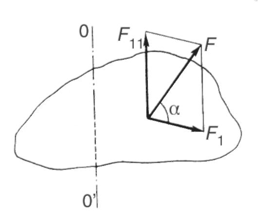
The basic equation of the dynamics of rotational motion
Let a rigid body acted upon by external forces turn through a sufficiently small angle da. Let us equate the elementary work of all external forces during such a rotation [see Fig. (5.13)] elementary change in kinetic energy [see (5.33)]: M dα = Jω dω , whence:
That's what it is basicequation of rotational motion dynamics. From (5.35) it can be seen that the moment of inertia characterizes the inertial properties of the body in rotational motion: under the action of external forces, the angular acceleration of the body is the greater, the smaller the moment of inertia of the body.
The basic equation for rotational motion plays the same role as Newton's second law for translational. Physical quantities, entering into this equation, are similar respectively to force, mass and acceleration.
From (5.34) it follows that:
The derivative of the angular momentum of the body with respect to time is equal to the resultant moment of all external forces.
The dependence of angular acceleration on the moment of force and moment of inertia can be demonstrated using
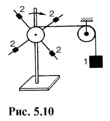
power of the device shown in Fig. 5.10. under the influence of the load 1, suspended on a thread thrown over a block, the crosspiece rotates rapidly. Moving weights 2 at different distances from the axis of rotation, you can change the moment of inertia of the cross. By changing loads, i.e. moments of forces, and the moment of inertia, it can be seen that the angular acceleration increases with an increase in the moment of force or a decrease in the moment of inertia.
5.3. LAW OF CONSERVATION OF MOMENTUM TORQUE
Consider special case rotational motion, when the total moment of external forces zero. As seen from (5.37), dl/dt= 0 at M = 0, whence
This position is known as the law of conservation of angular momentum: if the total momentum of all external forces acting on a body is zero, then the momentum of this body remains constant.
Omitting the proof, we note that the law of conservation of angular momentum is valid not only for an absolutely rigid body.
The most interesting applications of this law are connected with the rotation of a system of bodies around a common axis. In this case, it is necessary to take into account the vector nature of the angular momentum and angular velocities. So, for a system consisting of N bodies rotating around a common axis, the law of conservation of angular momentum can be written in the form:
Let's consider some examples illustrating this law.
A gymnast performing somersaults (Fig. 5.11), in initial phase bends the knees and presses them to the chest, thereby reducing the moment of inertia and increasing the angular velocity of rotation around a horizontal axis passing through the center of mass. At the end of the jump, the body straightens, the moment of inertia increases, and the angular velocity decreases. A figure skater who rotates around a vertical axis (Fig. 5.12) at the beginning of the rotation brings his hands closer to the body, thereby reducing the moment of inertia and increasing the angular velocity. At the end of the rotation, reverse process: When the arms are extended, the moment of inertia increases and the angular velocity decreases, which makes it easy to stop.

The same phenomenon can be demonstrated on the Zhukovsky bench, which is a light horizontal platform rotating with little friction around a vertical axis. When the position of the hands changes, the moment of inertia and angular velocity change (Fig. 5.13), the angular momentum remains constant. To enhance the demonstration effect in the hands of a person dumbbells. On Zhukovsky's bench, one can demonstrate the vector nature of the law of conservation of angular momentum.
The experimenter, standing on a fixed bench, receives from the assistant a bicycle wheel rotating around a vertical axis (Fig. 5.14, left). In this case, the moment of momentum of the system man and platform-wheel is determined only by the moment of momentum of the wheel:
here J h - the moment of inertia of the person and the platform; J K and ω κ - the moment of inertia and the angular velocity of the wheel. Since the moment of external forces about the vertical axis is zero, then L is preserved (L = const).
If the experimenter turns the axis of rotation of the wheel by 180 ° (Fig. 5.14, on the right), then the angular momentum of the wheel will be directed opposite to the original and equal to J K ω K . Since the vector of momentum of the wheel changes, and the moment of momentum of the system is preserved, then the moment of momentum of the person and the platform must inevitably change, it will no longer be equal to zero 1 . The angular momentum of the system in this case
1 A slight discrepancy between the axis of the wheel and the axis of rotation of the platform can be neglected.


Using formula (5.42), one can approximately estimate the moment of inertia of the human body together with the platform, for which it is necessary to measure ω κ , ω 4 and find J k . The method for measuring the angular velocities of uniform rotation is known to the reader. Knowing the wheel mass and assuming that the mass is mainly distributed along the rim, J k can be determined from formula (5.22). To reduce the error, you can weight the rim of a bicycle wheel by laying special tires on it. The person should be located symmetrically to the axis of rotation.
A simpler version of the above demonstration consists in the fact that a person standing on Zhukovsky's bench himself sets in rotation a wheel that he holds on a vertical axis. At the same time, the person and the platform begin to rotate in opposite sides(Fig. 5.15).
5.4. THE CONCEPT OF FREE AXES OF ROTATION
A body rotating about a fixed axis generally acts on bearings or other devices that keep the position of that axis unchanged. At high angular velocities and moments of inertia, these effects can be significant. However, in any body, you can choose such axes, the direction of which during rotation will be preserved without any special devices. To understand what condition the choice of such axes must satisfy, consider the following example.

Comparing (5.43) with the coordinates of the center of mass, we notice that the forces acting on the axis are balanced if the axis of rotation passes through the center of mass.
Thus, if the axis of rotation passes perpendicular to the rod through the center of mass, then there will be no impact on this axis from the side of the rotating body. If at the same time the bearings are removed, then the axis of rotation will begin to move, keeping its position in space unchanged, and the body will continue to rotate around this axis.
The axes of rotation, which, without special fixing, retain their direction in space, are called free. Examples of such axes are the axes of rotation of the Earth and the spinning top, the axis of any thrown and freely rotating body, etc.
A body of arbitrary shape always has at least three mutually perpendicular axes passing through the center of mass, which can be free axes of rotation. These axes are called the principal axes of inertia. Although all three main axes of inertia are free, rotation around the axis with the largest moment of inertia will be the most stable. The fact is that as a result of the inevitable action of external forces, such as friction, and also due to the fact that it is difficult to set the rotation exactly around a certain axis, the rotation around the remaining free axes is unstable.
In some cases, when a body rotates about a free axis with a small moment of inertia, it itself changes this axis to the axis with the largest moment.
This phenomenon is demonstrated by the following experiment. A cylindrical rod is suspended from the electric motor on a thread, which can rotate around its geometric axis (Fig. 5.17, a). Moment of inertia about this axis J 1 \u003d tR 2 / 2. With a sufficiently large angular velocity, the stick will change its position (Fig. 5.17, b). The moment of inertia about the new axis is J 2 = ml 2/12. If l 2 >6R 2 , then J 2 > J 1 . Rotation around the new axis will be stable.
The reader can independently verify from experience that the rotation of a thrown matchbox is stable relative to an axis passing perpendicular to the larger face, and unstable or less stable relative to axes passing perpendicular to other faces (see Fig. 5.8).
The rotation of animals and humans in free flight and during various jumps occurs around free axes with the largest or smallest moment of inertia. Since the position of the center of mass depends on the posture of the body, there will be different free axes for different postures.

5.5. THE CONCEPT OF DEGREES OF FREEDOM
The position of a free material point in space is given by three independent coordinates: x, y, z. If the point is not free, but moves, for example, along some surface, then not all three coordinates will be independent.

Independent variables characterizing the position mechanical system are called degrees of freedom.
A free material point has three degrees of freedom, in the considered example - two degrees of freedom. Since the molecule of a monatomic gas can be considered as a material point, therefore, such a free molecule also has three degrees of freedom.
Some more examples.
Two material points 1 and 2 are rigidly connected to each other. The position of both points is given by six coordinates x 1 , y 1 , z 1 , x 2 , y 2 , z 2 , on which one restriction and one connection are imposed, mathematically expressed in the form of an equation:
Physically, this means that the distance between material points is always l. In this case, the number of degrees of freedom is 5. The considered example is a model of a diatomic molecule.
Three material points 1, 2 and 3 are rigidly connected with each other. friend. Nine coordinates characterize the position of such a system: x1, y1, z1, x2, y2, z2, x 3 , y 3 , z 3 . However, three connections between points determine the independence of only six coordinates. The system has six degrees of freedom. Since the position of three points that do not lie on one straight line uniquely determines the position of a rigid body, the rigid body also has six degrees of freedom.
Triatomic and polyatomic molecules have the same number of degrees of freedom (six) if these molecules are considered as rigid formations.
1 If for the dependent coordinate from (5.44) an imaginary value is obtained, this means that the chosen independent coordinates do not correspond to any points located on a sphere of a given radius.
In real polyatomic molecules, atoms are in oscillatory motions, so the number of degrees of freedom of such molecules is more than six.
The number of degrees of freedom determines not only the number of independent variables characterizing the position of the mechanical system, but also, which is very important, the number of independent displacements of the system. Thus, three degrees of freedom of a free material point mean that any displacement of a point can be decomposed into independent displacements along three coordinate axes. Since a point has no dimensions, it makes no sense to talk about its rotation. So, a material point has three degrees of freedom of translational motion. A material point on a plane, sphere or other surface has two degrees of freedom of translational motion. The movement of a material point along a curve (a conditional example is the movement of a train along rails) corresponds to one degree of freedom of translational motion.
A rigid body rotating around a fixed axis has one degree of freedom of rotational motion. The train wheel has two degrees of freedom: one is rotational, and the other is translational (moving the wheel axis along the rail). Six degrees of freedom of a rigid body means that any displacement of this body can be decomposed into components: the displacement of the center of mass is decomposed into three translational movements along the coordinate axes, and the rotation consists of three simpler rotations about the coordinate axes passing through the center of mass.
On fig. 5.18-5.20 shows hinged joints corresponding to one, two and three degrees of freedom.

Rice. 5.18

Rice. 5.19
Rice. 5.20
5.6. CENTRIFUGING
Centrifugation is the process of separation (separation) of inhomogeneous systems, such as particles from liquids in which they are located, due to their rotation.
Consider the separation of inhomogeneous systems in the gravity field. Let us assume that there is an aqueous suspension of particles of various densities. Over time, due to the action of gravity and buoyancy F A stratification of particles occurs: particles with a density greater than that of water sink, particles with a density lower than that of water float. The resulting force acting, for example, on a denser individual particle is:
Where ρ 1 is the density of the substance of the particle; ρ is the density of water; V is the volume of the particle.
If the values of ρ 1 and ρ differ little from each other, then the force Fp is small and the separation (deposition) occurs rather slowly. In a centrifuge (separator) such separation is carried out forcibly by rotating the medium to be separated.
Consider the physics of this phenomenon.
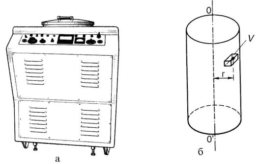
Let the working volume of the centrifuge (Fig. 5.21: a - appearance; b - scheme of the working volume) be completely occupied by any homogeneous liquid. Mentally select a small volume V this liquid, located at a distance r from the axis of rotation OO". With uniform rotation of the centrifuge on the selected volume, in addition to gravity and buoyancy force, which balance each other, a centripetal force acts. This is a force from the side of the liquid surrounding the volume. It is naturally directed towards the axis of rotation and is equal to:
Where ρ is the density of the liquid.
Let us now assume that the allocated volume V is a separated particle, the substance density of which is ρ 1 (ρ 1 Φ ρ). The force acting on the particle from the side of the surrounding fluid will not change, as can be seen from formula (5.45).
In order for the particle to rotate together with the liquid, a centripetal force must act on it, equal to:
Where m 1 is the mass of the particle, and ρ 1 is the density corresponding to it.
Rice. 5.21
If F> F1, then the particle moves towards the axis of rotation. If F< F1, then the impact on the particle from the liquid will not be enough to keep it on a circular trajectory, and the particle will begin to move to the periphery by inertia. The separation effect is determined by the excess force F, acting from the side of the liquid on the selected particle, over the value of the centripetal force F 1, which determines the movement in a circle:
This expression shows that the effect of centrifugation is greater, the greater the difference between the densities of the separated particles and liquid, and also significantly depends on the angular velocity of rotation 1 .
Compare centrifugation separation with gravity separation:

1 Gravity and buoyancy are not taken into account when deriving formula (5.47), since they are directed along the axis of rotation and do not have a fundamental effect on centrifugation.
Ultracentrifuges are capable of separating particles smaller than 100 nm suspended or dissolved in a liquid. They have found wide application in biomedical research for the separation of biopolymers, viruses, and subcellular particles.
The speed of separation is especially important in biological and biophysical research, since the state of the objects under study can change significantly over time.
The best definition of torque is the tendency of a force to rotate an object about an axis, fulcrum, or pivot point. Torque can be calculated using force and moment arm (perpendicular distance from the axis to the line of action of the force), or using moment of inertia and angular acceleration.
Steps
Using force and leverage
-
Determine the forces acting on the body and the corresponding moments. If the force is not perpendicular to the moment arm under consideration (i.e. it acts at an angle), then you may need to find its components using trigonometric functions such as sine or cosine.
- The force component considered will depend on the perpendicular force equivalent.
- Imagine a horizontal rod, to which a force of 10 N must be applied at an angle of 30° above the horizontal plane in order to rotate it around the center.
- Since you need to use a force that is not perpendicular to the moment arm, you need the vertical component of the force to rotate the rod.
- Therefore, one must consider the y-component, or use F = 10sin30° N.
-
Use the moment equation, τ = Fr, and simply replace the variables with the given or received data.
- A simple example: Imagine a 30 kg child sitting on one end of a seesaw. The length of one side of the swing is 1.5 m.
- Because the pivot of the swing is in the center, you don't need to multiply the length.
- You need to determine the force exerted by the child using mass and acceleration.
- Since the mass is given, you need to multiply it by the acceleration free fall, g, equal to 9.81 m / s 2. Hence:
- Now you have all the necessary data to use the moment equation:
-
Use the signs (plus or minus) to show the direction of the moment. If the force rotates the body clockwise, then the moment is negative. If the force rotates the body counterclockwise, then the moment is positive.
- In the case of multiple applied forces, simply add up all the moments in the body.
- Because each force tends to cause a different direction of rotation, it is important to use the rotation sign to keep track of the direction of each force.
- For example, two forces were applied to the rim of a wheel having a diameter of 0.050 m, F 1 = 10.0 N, directed clockwise, and F 2 = 9.0 N, directed counterclockwise.
- Since the given body is a circle, the fixed axis is its center. You need to divide the diameter to get the radius. The size of the radius will serve as the shoulder of the moment. Therefore, the radius is 0.025 m.
- For clarity, we can solve separate equations for each of the moments arising from the corresponding force.
- For force 1, the action is directed clockwise, therefore, the moment it creates is negative:
- For force 2, the action is directed counterclockwise, therefore, the moment it creates is positive:
- Now we can add up all the moments to get the resulting torque:
Using moment of inertia and angular acceleration
-
To begin solving the problem, understand how the moment of inertia of a body works. The moment of inertia of a body is the body's resistance to rotational motion. The moment of inertia depends on both the mass and the nature of its distribution.
- To understand this clearly, imagine two cylinders of the same diameter but different masses.
- Imagine that you need to rotate both cylinders around their central axis.
- Obviously, a cylinder with more mass will be harder to turn than another cylinder because it is "heavier".
- Now imagine two cylinders of different diameters but the same mass. To look cylindrical and have different masses, but at the same time have different diameters, the shape, or mass distribution, of both cylinders must be different.
- A larger diameter cylinder will look like a flat, rounded plate, while a smaller one will look like a solid tube of fabric.
- A cylinder with a larger diameter will be harder to turn because you need to apply more force to overcome the longer moment arm.
-
Select the equation you will use to calculate the moment of inertia. There are several equations that can be used for this.
- The first equation is the simplest: the summation of the masses and moment arms of all particles.
- This equation is used for material points, or particles. An ideal particle is a body that has mass but does not occupy space.
- In other words, the only significant characteristic of this body is its mass; you don't need to know its size, shape, or structure.
- The idea of a material particle is widely used in physics to simplify calculations and use ideal and theoretical schemes.
- Now imagine an object like a hollow cylinder or a solid uniform sphere. These objects have a clear and defined shape, size and structure.
- Therefore, you cannot consider them as a material point.
- Fortunately, formulas that apply to some common objects can be used:
-
Find the moment of inertia. To start calculating the torque, you need to find the moment of inertia. Use the following example as a guide:
- Two small “weights” weighing 5.0 kg and 7.0 kg are mounted at a distance of 4.0 m from each other on a light rod (whose mass can be neglected). The axis of rotation is in the middle of the rod. The rod spins up from rest to an angular velocity of 30.0 rad/s in 3.00 s. Calculate the generated torque.
- Since the axis of rotation is in the middle of the rod, the moment arm of both weights is equal to half of its length, i.e. 2.0 m
- Since the shape, size and structure of the “weights” is not specified, we can assume that the weights are material particles.
- The moment of inertia can be calculated as follows:
-
Find the angular acceleration, α. To calculate the angular acceleration, you can use the formula α= at/r.
- The first formula, α= at/r, can be used if the tangential acceleration and radius are given.
- Tangential acceleration is an acceleration directed tangentially to the direction of motion.
- Imagine an object moving along a curved path. The tangential acceleration is simply its linear acceleration at any point along the way.
- In the case of the second formula, it is easiest to illustrate it by relating it to concepts from kinematics: displacement, linear velocity and linear acceleration.
- Displacement is the distance traveled by an object (SI unit - meters, m); linear speed is a measure of the change in displacement per unit of time (SI unit - m / s); linear acceleration is an indicator of the change in linear speed per unit of time (SI unit - m / s 2).
- Now let's look at the analogues of these quantities during rotational motion: angular displacement, θ - the angle of rotation of a certain point or segment (SI unit - rad); angular velocity, ω - change in angular displacement per unit of time (SI unit - rad/s); and angular acceleration, α - change in angular velocity per unit time (SI unit - rad / s 2).
- Returning to our example, we were given data for angular momentum and time. Since the rotation started from rest, the initial angular velocity is 0. We can use the equation to find:
-
Use the equation, τ = Iα, to find the torque. Just replace the variables with the answers from the previous steps.
- You may notice that the unit "rad" doesn't fit in with our units of measurement, as it's considered a dimensionless quantity.
- This means that you can ignore it and continue with your calculations.
- For unit analysis, we can express angular acceleration in s -2 .
- In the first method, if the body is a circle and its axis of rotation is in the center, then it is not necessary to calculate the components of the force (provided that the force is not applied obliquely), since the force lies on the tangent to the circle, i.e. perpendicular to the moment arm.
- If you find it difficult to imagine how the rotation occurs, then take a pen and try to recreate the problem. For a more accurate reproduction, do not forget to copy the position of the axis of rotation and the direction of the applied force.